How to Use esp 32 wroom diagram: Examples, Pinouts, and Specs
Introduction
The ESP32 WROOM module, manufactured by SobreCarey, is a powerful and versatile microcontroller module that integrates both Wi-Fi and Bluetooth capabilities. It is widely used in Internet of Things (IoT) applications, enabling seamless wireless communication and control. The module is designed for low-power consumption and high performance, making it ideal for smart devices, home automation, wearable electronics, and industrial IoT systems.
The ESP32 WROOM diagram provides a schematic representation of the module, detailing its pinout and internal connections. This documentation will guide users in understanding the module's layout and how to integrate it into their projects.
Explore Projects Built with esp 32 wroom diagram


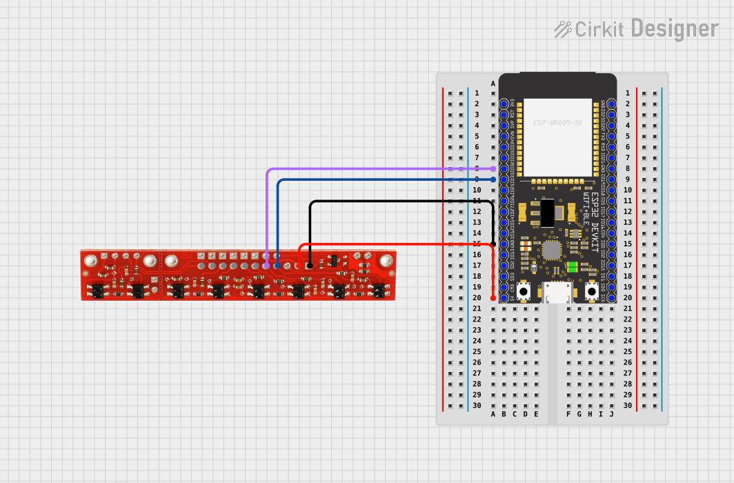
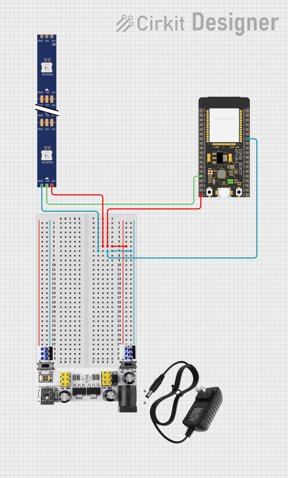
Explore Projects Built with esp 32 wroom diagram
Technical Specifications
The ESP32 WROOM module is built for robust wireless communication and efficient processing. Below are its key technical specifications:
- Microcontroller: Dual-core Xtensa® 32-bit LX6
- Clock Speed: Up to 240 MHz
- Flash Memory: 4 MB (varies by model)
- RAM: 520 KB SRAM
- Wi-Fi: 802.11 b/g/n
- Bluetooth: v4.2 BR/EDR and BLE
- Operating Voltage: 3.0V to 3.6V
- Power Consumption: Ultra-low power consumption in sleep modes
- GPIO Pins: 34 (multipurpose)
- Communication Protocols: UART, SPI, I2C, I2S, PWM, ADC, DAC
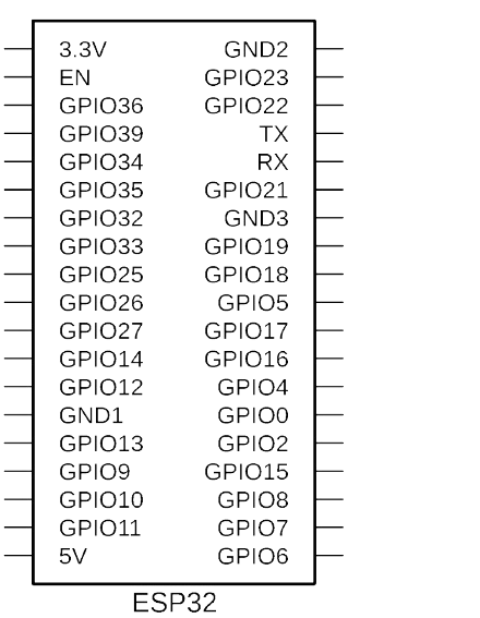
Pin Configuration and Descriptions
The ESP32 WROOM module has a total of 38 pins. Below is the pinout description:
| Pin Number | Pin Name | Description |
|---|---|---|
| 1 | EN |
Enable pin. Active high. Used to reset the module. |
| 2 | IO0 |
GPIO0. Can be used for general-purpose I/O or boot mode selection. |
| 3 | IO1 |
GPIO1. General-purpose I/O. |
| 4 | IO2 |
GPIO2. General-purpose I/O. |
| 5 | IO3 |
GPIO3. General-purpose I/O. |
| 6 | GND |
Ground. Connect to the system ground. |
| 7 | 3V3 |
3.3V power supply input. |
| 8 | TXD0 |
UART0 Transmit pin. Used for serial communication. |
| 9 | RXD0 |
UART0 Receive pin. Used for serial communication. |
| 10 | IO4 |
GPIO4. General-purpose I/O. |
| ... | ... | ... (Refer to the full datasheet for all pin descriptions.) |
Note: Some pins have multiple functions, such as ADC, DAC, or PWM. Refer to the ESP32 WROOM datasheet for detailed pin multiplexing information.
Usage Instructions
How to Use the ESP32 WROOM in a Circuit
- Power Supply: Ensure the module is powered with a stable 3.3V supply. Avoid exceeding 3.6V to prevent damage.
- Connections:
- Connect the
GNDpin to the system ground. - Use the
ENpin to reset the module if needed. - For UART communication, connect
TXD0andRXD0to the respective pins on your microcontroller or USB-to-serial adapter.
- Connect the
- Programming:
- Use the GPIO0 pin to set the module into boot mode for programming.
- Connect the module to a computer via a USB-to-serial adapter and use the Arduino IDE or ESP-IDF for programming.
Example: Connecting to an Arduino UNO
Below is an example of how to connect the ESP32 WROOM to an Arduino UNO for basic communication:
| ESP32 WROOM Pin | Arduino UNO Pin |
|---|---|
TXD0 |
RX |
RXD0 |
TX |
GND |
GND |
3V3 |
3.3V |
Example Code: Blink an LED
The following code demonstrates how to blink an LED connected to GPIO2 of the ESP32 WROOM module:
// Define the GPIO pin for the LED
#define LED_PIN 2

void setup() {
  // Set the LED pin as an output
  pinMode(LED_PIN, OUTPUT);
}

void loop() {
  // Turn the LED on
  digitalWrite(LED_PIN, HIGH);
  delay(1000); // Wait for 1 second

  // Turn the LED off
  digitalWrite(LED_PIN, LOW);
  delay(1000); // Wait for 1 second
}
Important: Ensure the LED is connected to GPIO2 with a current-limiting resistor (e.g., 220Ω) to prevent damage.
Best Practices
- Use decoupling capacitors near the power pins to stabilize the power supply.
- Avoid using GPIO pins that are reserved for internal functions (e.g., GPIO6 to GPIO11).
- Use level shifters if interfacing with 5V logic devices.
Troubleshooting and FAQs
Common Issues
Module Not Responding:
- Ensure the
ENpin is pulled high. - Verify the power supply voltage is within the acceptable range (3.0V to 3.6V).
- Ensure the
Cannot Upload Code:
- Check the connection of GPIO0 to ground during boot mode.
- Verify the correct COM port and board settings in the Arduino IDE.
Wi-Fi Connection Fails:
- Ensure the SSID and password are correct.
- Check for interference or weak signal strength.
Solutions and Tips
- Use a multimeter to verify all connections and power supply levels.
- Update the ESP32 board package in the Arduino IDE to the latest version.
- If the module overheats, check for short circuits or excessive current draw.
By following this documentation, users can effectively integrate the ESP32 WROOM module into their projects and troubleshoot common issues. For more advanced configurations, refer to the official datasheet and programming guides provided by SobreCarey.