How to Use 4S 30A BMS: Examples, Pinouts, and Specs
4S 30A Battery Management System (BMS) Documentation
1. Introduction
The 4S 30A Battery Management System (BMS) is a critical component for managing and protecting lithium-ion battery packs configured in a 4-series (4S) arrangement. It is designed to handle a maximum continuous current of 30A, making it suitable for medium to high-power applications. The BMS ensures the safety, longevity, and efficiency of the battery pack by monitoring individual cell voltages, balancing charge levels, and providing protection against overcharging, over-discharging, short circuits, and overcurrent conditions.
Common Applications
- Electric bicycles and scooters
- Portable power banks
- Solar energy storage systems
- Uninterruptible Power Supplies (UPS)
- Robotics and DIY electronics projects
- Power tools and other battery-powered devices
2. Technical Specifications
The following table outlines the key technical details of the 4S 30A BMS:
| Parameter | Value |
|---|---|
| Battery Configuration | 4 Series (4S) |
| Maximum Continuous Current | 30A |
| Overcharge Protection | 4.25V ± 0.05V per cell |
| Over-discharge Protection | 2.7V ± 0.05V per cell |
| Balancing Voltage | 4.2V per cell |
| Balancing Current | 30mA |
| Operating Voltage Range | 8V - 16.8V |
| Short Circuit Protection | Yes |
| Overcurrent Protection | Yes (30A) |
| Operating Temperature Range | -20°C to 60°C |
| Dimensions | ~60mm x 20mm x 3mm |
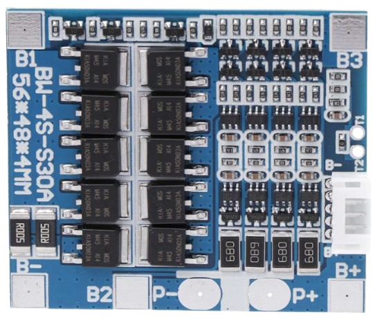
Pin Configuration and Descriptions
The 4S 30A BMS typically has the following pin configuration:
| Pin Name | Description |
|---|---|
| B- | Battery pack negative terminal |
| B1 | Connection to the positive terminal of the first cell in the series |
| B2 | Connection to the positive terminal of the second cell in the series |
| B3 | Connection to the positive terminal of the third cell in the series |
| B+ | Battery pack positive terminal |
| P- | Power output negative terminal (connect to load or charger negative terminal) |
| P+ | Power output positive terminal (connect to load or charger positive terminal) |
3. Usage Instructions
Connecting the 4S 30A BMS to a Battery Pack
Prepare the Battery Pack:
- Ensure the battery pack consists of four series-connected lithium-ion cells.
- Verify that all cells are balanced (i.e., have similar voltages) before connecting the BMS.
Connect the BMS:
- Connect the B- pin to the negative terminal of the battery pack.
- Connect the B1, B2, and B3 pins to the positive terminals of the first, second, and third cells, respectively.
- Connect the B+ pin to the positive terminal of the battery pack.
- Connect the P- and P+ pins to the load or charger as required.
Verify Connections:
- Double-check all connections to ensure they are secure and correctly aligned with the pin configuration.
Power On:
- Once all connections are verified, the BMS will automatically begin monitoring and protecting the battery pack.
Important Considerations and Best Practices
- Cell Matching: Use cells with similar capacities, internal resistances, and charge levels to ensure optimal performance.
- Heat Dissipation: Ensure adequate ventilation or heat sinking for the BMS, especially in high-current applications.
- Avoid Overloading: Do not exceed the maximum continuous current rating of 30A.
- Wiring: Use appropriately rated wires for the current to prevent overheating or voltage drops.
- Testing: Test the BMS with a multimeter to confirm proper operation before full-scale use.
4. Example Application with Arduino UNO
The 4S 30A BMS can be used in conjunction with an Arduino UNO to monitor battery pack voltage. Below is an example code to read the total battery voltage using an analog input pin.
Circuit Diagram
- Connect the B+ terminal of the BMS to the positive input of a voltage divider circuit.
- Connect the B- terminal of the BMS to the ground of the Arduino.
- Use a voltage divider to step down the battery voltage to a range suitable for the Arduino's analog input (0-5V).
Arduino Code
// Define the analog pin connected to the voltage divider
const int voltagePin = A0;

// Define the voltage divider ratio (adjust based on your resistor values)
const float voltageDividerRatio = 5.7; // Example: 100k and 22k resistors

// Define the reference voltage of the Arduino (5V for most boards)
const float referenceVoltage = 5.0;

void setup() {
  // Initialize serial communication for debugging
  Serial.begin(9600);
}

void loop() {
  // Read the analog value from the voltage divider
  int analogValue = analogRead(voltagePin);

  // Convert the analog value to the actual battery voltage
  float batteryVoltage = (analogValue * referenceVoltage / 1023.0) * voltageDividerRatio;

  // Print the battery voltage to the Serial Monitor
  Serial.print("Battery Voltage: ");
  Serial.print(batteryVoltage);
  Serial.println(" V");

  // Wait for 1 second before the next reading
  delay(1000);
}
Note: Ensure the voltage divider is correctly calculated to avoid exceeding the Arduino's input voltage limit (5V).
5. Troubleshooting and FAQs
Common Issues and Solutions
| Issue | Possible Cause | Solution |
|---|---|---|
| BMS not powering on | Incorrect wiring or loose connections | Verify all connections and ensure proper wiring as per the pin configuration. |
| Battery pack not charging | Overcharge protection activated | Check individual cell voltages and ensure none exceed 4.25V. |
| Battery pack discharges too quickly | Cells are unbalanced or degraded | Balance the cells or replace degraded cells. |
| BMS overheating during operation | Exceeding maximum current rating | Reduce the load current or improve heat dissipation. |
| Short circuit protection triggers often | Faulty wiring or load issues | Inspect wiring and ensure the load is within the BMS's current rating. |
Frequently Asked Questions (FAQs)
Can I use this BMS with fewer than 4 cells?
- No, this BMS is specifically designed for 4-series (4S) lithium-ion battery packs.
What happens if one cell is over-discharged?
- The BMS will cut off the output to protect the cell from damage. Balance or replace the cell before reconnecting.
Can I use this BMS for LiFePO4 batteries?
- No, this BMS is designed for lithium-ion cells with a nominal voltage of 3.7V per cell. LiFePO4 cells have different voltage requirements.
How do I know if the BMS is balancing the cells?
- The BMS will automatically balance cells when their voltages exceed 4.2V. You can measure individual cell voltages to confirm.
This documentation provides a comprehensive guide to understanding, using, and troubleshooting the 4S 30A BMS. By following the instructions and best practices outlined here, you can ensure safe and efficient operation of your lithium-ion battery pack.
Explore Projects Built with 4S 30A BMS


Explore Projects Built with 4S 30A BMS