Cirkit Designer Logo
Cirkit Designer
Your all-in-one circuit design IDE
Home / 
Component Documentation

How to Use KCU105: Examples, Pinouts, and Specs

Image of KCU105
Cirkit Designer LogoDesign with KCU105 in Cirkit Designer

Introduction

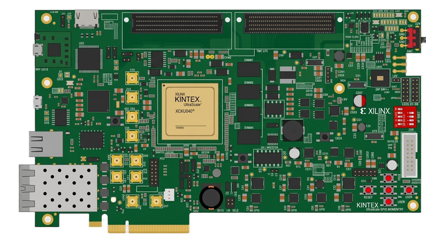
The KCU105 is a development board manufactured by AMD (formerly Xilinx) and designed for the Kintex-7 FPGA family. It serves as a versatile platform for prototyping and testing FPGA-based designs. The board is equipped with a variety of interfaces, including HDMI, USB, Ethernet, and PCIe, making it ideal for applications in digital signal processing, communications, embedded systems, and high-performance computing.

Explore Projects Built with KCU105

Use Cirkit Designer to design, explore, and prototype these projects online. Some projects support real-time simulation. Click "Open Project" to start designing instantly!
Arduino UNO-Based Smart Humidifier and Temperature Monitor with OLED Display
Image of Humidity Control: A project utilizing KCU105 in a practical application
This circuit is a smart environmental monitoring and control system. It uses an Arduino UNO to read data from a temperature-humidity sensor and a real-time clock, displays information on an OLED screen, and controls an exhaust fan and a humidifier via a relay module. The system is powered by a 5V power supply and includes a key switch for user input.
Cirkit Designer LogoOpen Project in Cirkit Designer
Arduino UNO Controlled Joystick Interface with LCD Feedback and Audio Alert
Image of 우주게임: A project utilizing KCU105 in a practical application
This circuit features an Arduino UNO microcontroller connected to a KY-023 Dual Axis Joystick Module, an I2C LCD 16x2 Screen, a Piezo Speaker, and a Pushbutton. The joystick provides two analog inputs to the Arduino for X and Y axis control, while the pushbutton is connected to a digital input for user interaction. The LCD screen displays information via I2C communication, and the Piezo Speaker is driven by a digital output from the Arduino for audio feedback.
Cirkit Designer LogoOpen Project in Cirkit Designer
Bluetooth-Controlled Multi-Function Arduino Nano Gadget
Image of Copy of Smarttt: A project utilizing KCU105 in a practical application
This is a portable, microcontroller-driven interactive device featuring Bluetooth connectivity, visual (RGB LED), auditory (loudspeaker), and haptic (vibration motor) feedback, user input (pushbutton), and a rechargeable power system (TP4056 with Li-ion battery).
Cirkit Designer LogoOpen Project in Cirkit Designer
Arduino Nano-Based Wireless Joystick and Motion Controller
Image of hand gesture: A project utilizing KCU105 in a practical application
This circuit features an Arduino Nano microcontroller interfaced with an HC-05 Bluetooth module, an MPU-6050 accelerometer/gyroscope, and a KY-023 Dual Axis Joystick Module. The Arduino Nano is powered by a 9V battery through a rocker switch and communicates with the HC-05 for Bluetooth connectivity, reads joystick positions from the KY-023 module via analog inputs, and communicates with the MPU-6050 over I2C to capture motion data. The circuit is likely designed for wireless control and motion sensing applications, such as a remote-controlled robot or a game controller.
Cirkit Designer LogoOpen Project in Cirkit Designer

Explore Projects Built with KCU105

Use Cirkit Designer to design, explore, and prototype these projects online. Some projects support real-time simulation. Click "Open Project" to start designing instantly!
Image of Humidity Control: A project utilizing KCU105 in a practical application
Arduino UNO-Based Smart Humidifier and Temperature Monitor with OLED Display
This circuit is a smart environmental monitoring and control system. It uses an Arduino UNO to read data from a temperature-humidity sensor and a real-time clock, displays information on an OLED screen, and controls an exhaust fan and a humidifier via a relay module. The system is powered by a 5V power supply and includes a key switch for user input.
Cirkit Designer LogoOpen Project in Cirkit Designer
Image of 우주게임: A project utilizing KCU105 in a practical application
Arduino UNO Controlled Joystick Interface with LCD Feedback and Audio Alert
This circuit features an Arduino UNO microcontroller connected to a KY-023 Dual Axis Joystick Module, an I2C LCD 16x2 Screen, a Piezo Speaker, and a Pushbutton. The joystick provides two analog inputs to the Arduino for X and Y axis control, while the pushbutton is connected to a digital input for user interaction. The LCD screen displays information via I2C communication, and the Piezo Speaker is driven by a digital output from the Arduino for audio feedback.
Cirkit Designer LogoOpen Project in Cirkit Designer
Image of Copy of Smarttt: A project utilizing KCU105 in a practical application
Bluetooth-Controlled Multi-Function Arduino Nano Gadget
This is a portable, microcontroller-driven interactive device featuring Bluetooth connectivity, visual (RGB LED), auditory (loudspeaker), and haptic (vibration motor) feedback, user input (pushbutton), and a rechargeable power system (TP4056 with Li-ion battery).
Cirkit Designer LogoOpen Project in Cirkit Designer
Image of hand gesture: A project utilizing KCU105 in a practical application
Arduino Nano-Based Wireless Joystick and Motion Controller
This circuit features an Arduino Nano microcontroller interfaced with an HC-05 Bluetooth module, an MPU-6050 accelerometer/gyroscope, and a KY-023 Dual Axis Joystick Module. The Arduino Nano is powered by a 9V battery through a rocker switch and communicates with the HC-05 for Bluetooth connectivity, reads joystick positions from the KY-023 module via analog inputs, and communicates with the MPU-6050 over I2C to capture motion data. The circuit is likely designed for wireless control and motion sensing applications, such as a remote-controlled robot or a game controller.
Cirkit Designer LogoOpen Project in Cirkit Designer

Common Applications and Use Cases

  • Digital signal processing (DSP) applications
  • High-speed communication systems
  • Embedded system prototyping
  • Video and image processing
  • Hardware acceleration for machine learning and AI
  • PCIe-based system development

Technical Specifications

Key Technical Details

  • FPGA Device: Kintex-7 XC7K325T-2FFG900C
  • Memory:
    • 1 GB DDR3 SDRAM (64-bit wide)
    • 128 Mb Quad-SPI Flash
  • Interfaces:
    • HDMI input and output
    • USB 2.0 and USB-UART
    • Gigabit Ethernet
    • PCIe Gen2 x8
  • Clocking:
    • Programmable clock generator
    • On-board 200 MHz oscillator
  • Power Supply: 12V DC input
  • Debugging:
    • JTAG interface
    • On-board System Monitor for voltage and temperature monitoring

Pin Configuration and Descriptions

The KCU105 board has multiple connectors and interfaces. Below is a summary of key pin configurations:

FPGA I/O Banks

Bank Number Voltage Standard Description
Bank 13 1.8V General-purpose I/O
Bank 34 3.3V High-speed differential I/O
Bank 65 2.5V Dedicated for DDR3 memory

Key Connectors

Connector Pin Count Description
FMC (HPC) Connector 160 High-speed expansion for custom peripherals
PCIe Edge Connector 164 PCIe Gen2 x8 interface
HDMI Input/Output 19 Video input and output

Usage Instructions

How to Use the KCU105 in a Circuit

  1. Powering the Board:

    • Connect a 12V DC power supply to the power input jack.
    • Ensure the power switch is turned on.
  2. Programming the FPGA:

    • Use the JTAG interface to program the FPGA via Vivado Design Suite.
    • Alternatively, load a bitstream from the Quad-SPI Flash.
  3. Connecting Peripherals:

    • Use the FMC connector to attach custom hardware modules.
    • Connect HDMI cables for video input/output.
    • Use the USB-UART interface for serial communication with a host PC.
  4. Clock Configuration:

    • Configure the programmable clock generator using Vivado or external tools.
    • Ensure the clock frequency matches the requirements of your design.

Important Considerations and Best Practices

  • Power Supply: Always use a regulated 12V DC power supply to avoid damaging the board.
  • Thermal Management: The FPGA can generate significant heat during operation. Use the provided heat sink and ensure adequate airflow.
  • Signal Integrity: For high-speed signals (e.g., PCIe, HDMI), use high-quality cables and minimize trace lengths on custom hardware.
  • Vivado Compatibility: Ensure you are using a compatible version of Vivado Design Suite for programming and debugging.

Example Code for UART Communication with Arduino UNO

The KCU105 can communicate with an Arduino UNO via the USB-UART interface. Below is an example Arduino sketch for sending data to the KCU105:

// Arduino UNO UART Communication Example
// Sends a message to the KCU105 via the USB-UART interface.

void setup() {
  Serial.begin(9600); // Initialize UART at 9600 baud rate
  delay(1000);        // Wait for the serial connection to stabilize
}

void loop() {
  Serial.println("Hello, KCU105!"); // Send a message to the KCU105
  delay(1000);                      // Wait 1 second before sending again
}

On the KCU105, you can use a UART receiver module in your FPGA design to process the incoming data.

Troubleshooting and FAQs

Common Issues and Solutions

  1. The board does not power on:

    • Ensure the power supply is connected and providing 12V DC.
    • Check the power switch and ensure it is in the "ON" position.
    • Verify the power LED is lit.
  2. FPGA programming fails:

    • Confirm the JTAG cable is securely connected.
    • Ensure the correct bitstream file is selected in Vivado.
    • Check for any errors in the Vivado console output.
  3. No output on HDMI:

    • Verify the HDMI cables are properly connected.
    • Ensure the FPGA design includes an HDMI controller.
    • Check the clock configuration for the HDMI interface.
  4. Ethernet connection not working:

    • Confirm the Ethernet cable is connected to an active network.
    • Verify the FPGA design includes an Ethernet MAC and PHY interface.
    • Check the IP address configuration in your design.

FAQs

Q: Can I use the KCU105 with other FPGA families?
A: No, the KCU105 is specifically designed for the Kintex-7 FPGA family.

Q: What is the maximum clock frequency supported by the FPGA?
A: The Kintex-7 XC7K325T FPGA supports clock frequencies up to 400 MHz, depending on the design.

Q: Is the KCU105 compatible with Linux-based development tools?
A: Yes, the Vivado Design Suite is available for both Windows and Linux operating systems.

Q: Can I use the KCU105 for machine learning applications?
A: Yes, the KCU105 is suitable for hardware acceleration of machine learning algorithms, especially for applications requiring high-speed computation and parallelism.

Q: How do I update the firmware on the KCU105?
A: Firmware updates can be applied via the JTAG interface or by loading a new bitstream into the Quad-SPI Flash.

This concludes the documentation for the KCU105 development board. For further assistance, refer to the official AMD/Xilinx user guide or contact technical support.