How to Use servo tester : Examples, Pinouts, and Specs
Introduction
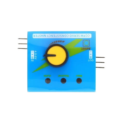
The ROBO MINDS Servo Tester (Part ID: 20052007) is a versatile device designed to test and control the position of servo motors by generating Pulse Width Modulation (PWM) signals. This component is essential for hobbyists, engineers, and developers working with servo motors in various applications such as robotics, RC vehicles, and automation systems.
Explore Projects Built with servo tester

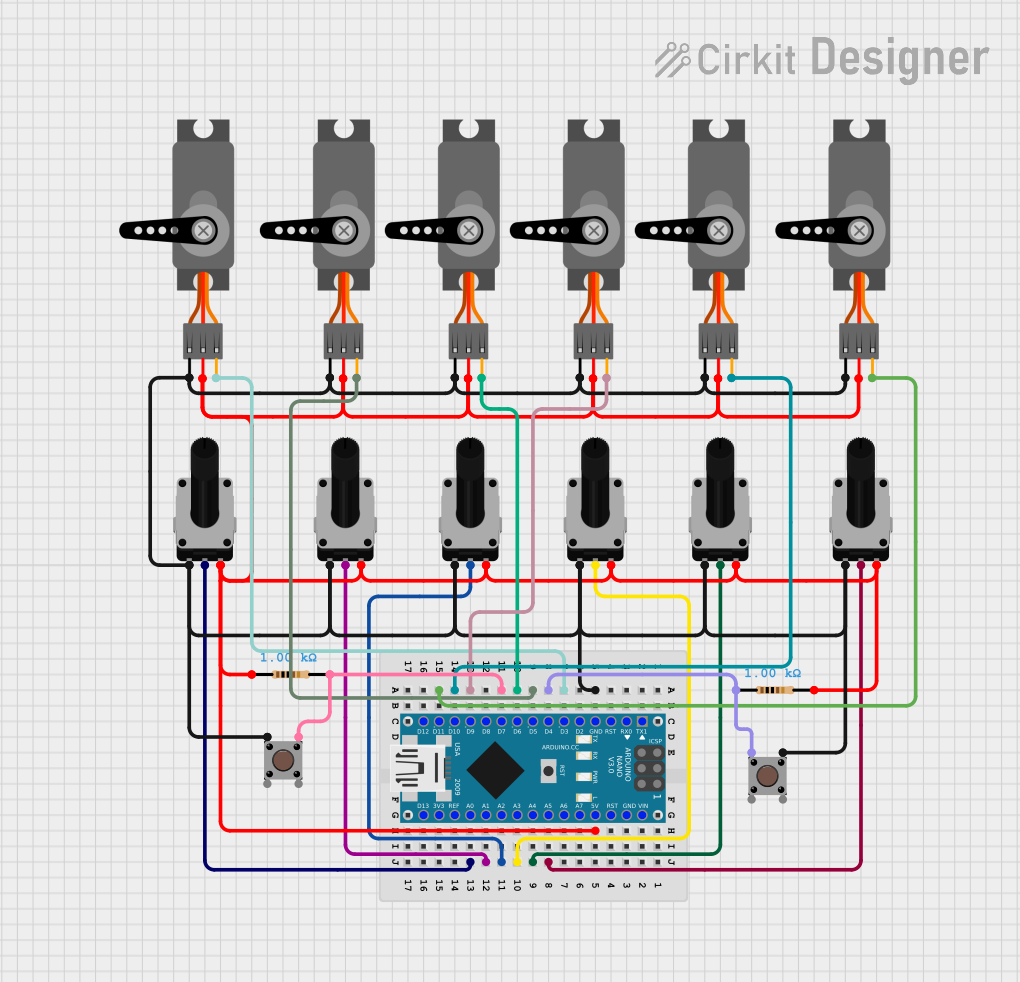
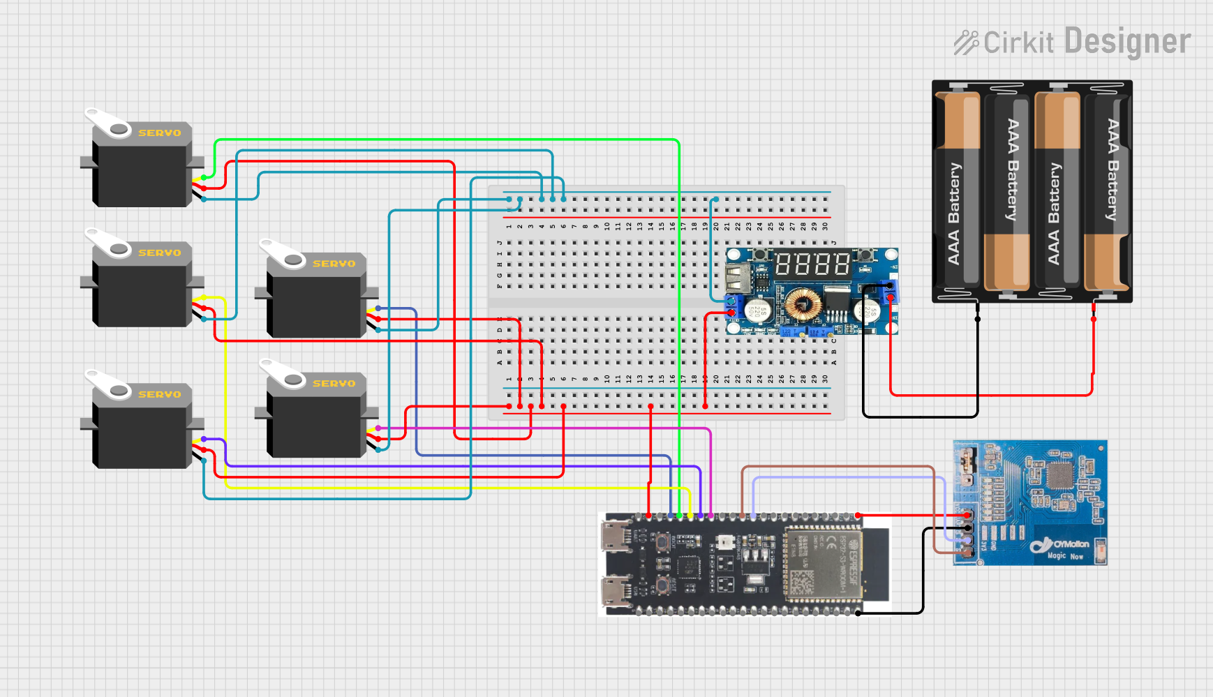
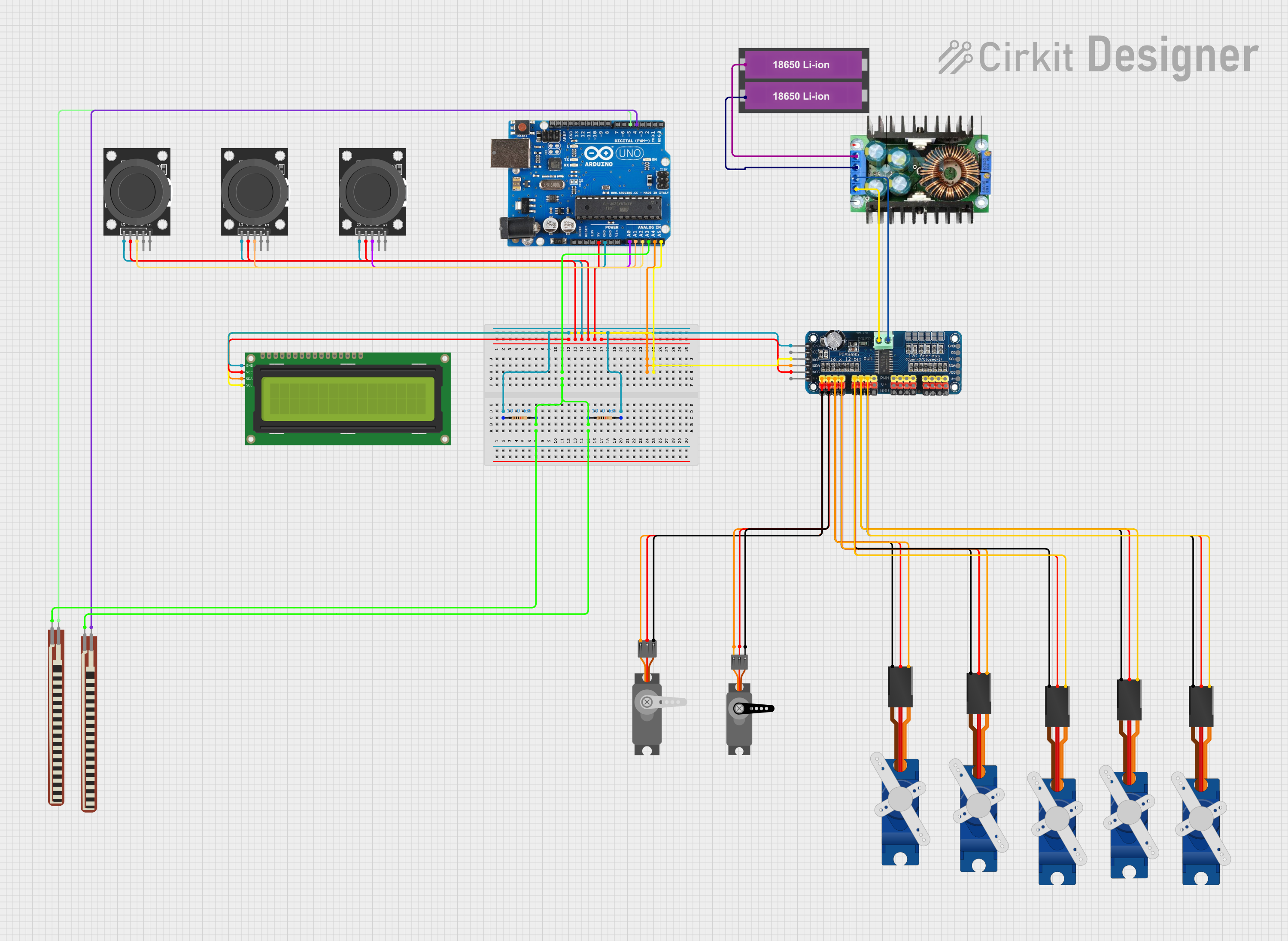
Explore Projects Built with servo tester
Common Applications and Use Cases
- Robotics: Testing and calibrating servo motors used in robotic arms and joints.
- RC Vehicles: Ensuring proper functionality of servos in remote-controlled cars, boats, and airplanes.
- Automation Systems: Controlling servo motors in automated machinery and equipment.
- Prototyping: Quickly testing servo motors during the development phase of projects.
Technical Specifications
Key Technical Details
| Parameter | Value |
|---|---|
| Operating Voltage | 4.8V - 6.0V |
| Operating Current | 10mA - 30mA |
| PWM Signal Output | 1ms - 2ms (50Hz) |
| Dimensions | 48mm x 42mm x 17mm |
| Weight | 15g |
| Operating Temperature | -10°C to 60°C |
Pin Configuration and Descriptions
| Pin Number | Pin Name | Description |
|---|---|---|
| 1 | VCC | Power supply input (4.8V - 6.0V) |
| 2 | GND | Ground |
| 3 | PWM | PWM signal output to the servo motor |
| 4 | MODE | Mode selection (Manual, Neutral, Auto) |
Usage Instructions
How to Use the Servo Tester in a Circuit
Power Connection:
- Connect the VCC pin to a power supply within the range of 4.8V to 6.0V.
- Connect the GND pin to the ground of the power supply.
Servo Connection:
- Connect the PWM pin to the signal input of the servo motor.
- Ensure the servo motor's power and ground are connected to the same power source as the servo tester.
Mode Selection:
- Use the MODE pin to select the desired mode of operation:
- Manual Mode: Adjust the servo position using a potentiometer.
- Neutral Mode: Set the servo to its neutral position (1.5ms PWM signal).
- Auto Mode: Sweep the servo back and forth automatically.
- Use the MODE pin to select the desired mode of operation:
Important Considerations and Best Practices
- Power Supply: Ensure the power supply voltage is within the specified range to avoid damaging the servo tester or the servo motor.
- Connections: Double-check all connections before powering up the circuit to prevent short circuits or incorrect signal transmission.
- Heat Dissipation: Avoid operating the servo tester in high-temperature environments to prevent overheating.
- Mode Selection: Use the mode selection feature appropriately to match the testing requirements of your servo motor.
Troubleshooting and FAQs
Common Issues and Solutions
Servo Motor Not Responding:
- Solution: Check the power supply connections and ensure the voltage is within the specified range. Verify that the PWM signal is correctly connected to the servo motor.
Erratic Servo Movement:
- Solution: Ensure the ground connections are secure and common between the servo tester and the servo motor. Check for any loose connections or interference in the signal line.
Overheating:
- Solution: Ensure proper ventilation around the servo tester. Avoid operating in high-temperature environments and check for any excessive current draw from the servo motor.
FAQs
Q1: Can I use the servo tester with any servo motor?
- A1: Yes, the servo tester is compatible with most standard servo motors that operate within the specified voltage range.
Q2: How do I switch between modes?
- A2: Use the MODE pin to select the desired mode. Refer to the pin configuration table for details on mode selection.
Q3: Can I use the servo tester with an Arduino UNO?
- A3: Yes, you can use the servo tester with an Arduino UNO. Below is an example code to control the servo tester using an Arduino UNO.
#include <Servo.h>

Servo myServo;  // Create a Servo object

void setup() {
  myServo.attach(9);  // Attach the servo to pin 9
}

void loop() {
  myServo.write(0);  // Move servo to 0 degrees
  delay(1000);       // Wait for 1 second
  myServo.write(90); // Move servo to 90 degrees
  delay(1000);       // Wait for 1 second
  myServo.write(180);// Move servo to 180 degrees
  delay(1000);       // Wait for 1 second
}
This code demonstrates how to control a servo motor connected to the servo tester using an Arduino UNO. The servo will move to 0, 90, and 180 degrees with a 1-second delay between each position.
By following this documentation, users can effectively utilize the ROBO MINDS Servo Tester (Part ID: 20052007) in their projects, ensuring accurate and reliable control of servo motors.