How to Use INA3221: Examples, Pinouts, and Specs
Introduction
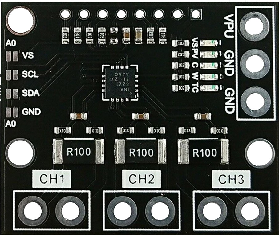
The INA3221 is a three-channel, high-side current and bus voltage monitor with an I2C interface, manufactured by Texas Instruments. This versatile component is designed to measure the current, voltage, and power of three different loads simultaneously. It is particularly useful in power management applications, such as battery-operated devices, power supplies, and energy monitoring systems.
Explore Projects Built with INA3221
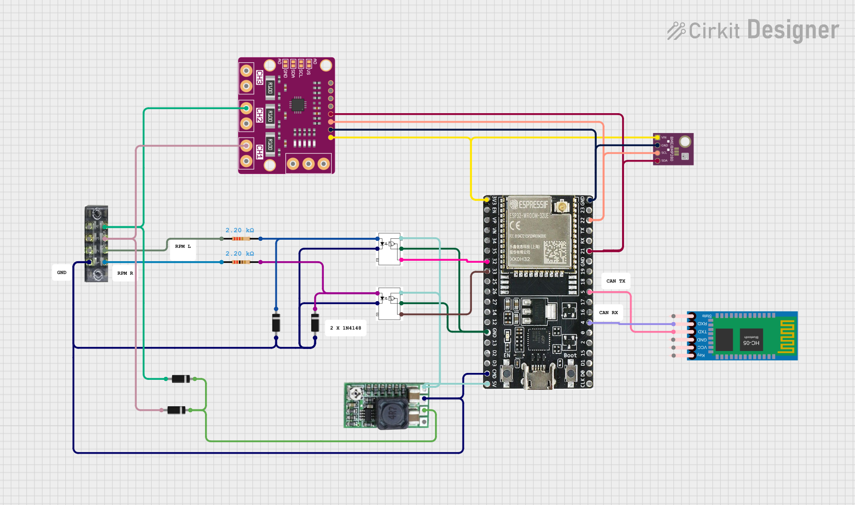

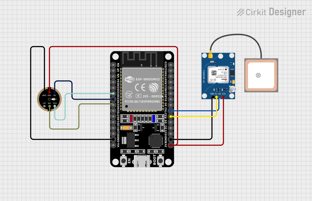

Explore Projects Built with INA3221
Technical Specifications
Key Technical Details
| Parameter | Value |
|---|---|
| Supply Voltage (Vcc) | 2.7V to 5.5V |
| Bus Voltage Range | 0V to 26V |
| Shunt Voltage Range | ±163.84mV |
| Current Measurement Range | Configurable via external shunt resistor |
| Communication Interface | I2C |
| Operating Temperature | -40°C to +125°C |
| Package | 16-pin TSSOP |
Pin Configuration and Descriptions
| Pin No. | Pin Name | Description |
|---|---|---|
| 1 | GND | Ground |
| 2 | VCC | Power Supply (2.7V to 5.5V) |
| 3 | SDA | I2C Data Line |
| 4 | SCL | I2C Clock Line |
| 5 | ALERT1 | Alert Output 1 |
| 6 | ALERT2 | Alert Output 2 |
| 7 | ALERT3 | Alert Output 3 |
| 8 | SHUNT1+ | Positive Input for Shunt Resistor 1 |
| 9 | SHUNT1- | Negative Input for Shunt Resistor 1 |
| 10 | SHUNT2+ | Positive Input for Shunt Resistor 2 |
| 11 | SHUNT2- | Negative Input for Shunt Resistor 2 |
| 12 | SHUNT3+ | Positive Input for Shunt Resistor 3 |
| 13 | SHUNT3- | Negative Input for Shunt Resistor 3 |
| 14 | BUS1 | Bus Voltage Input 1 |
| 15 | BUS2 | Bus Voltage Input 2 |
| 16 | BUS3 | Bus Voltage Input 3 |
Usage Instructions
How to Use the INA3221 in a Circuit
- Power Supply: Connect the VCC pin to a power supply within the range of 2.7V to 5.5V. Connect the GND pin to the ground of the circuit.
- I2C Communication: Connect the SDA and SCL pins to the corresponding I2C lines of your microcontroller. Pull-up resistors (typically 4.7kΩ) are required on these lines.
- Shunt Resistors: Connect the SHUNT+ and SHUNT- pins to the shunt resistors placed in series with the loads you want to monitor.
- Bus Voltage Inputs: Connect the BUS pins to the points in the circuit where you want to measure the bus voltage.
- Alert Outputs: If needed, connect the ALERT pins to the microcontroller or other monitoring systems to receive alerts based on predefined conditions.
Important Considerations and Best Practices
- Shunt Resistor Selection: Choose shunt resistors with appropriate values to ensure the voltage drop across them is within the ±163.84mV range.
- I2C Address: The INA3221 has a fixed I2C address. Ensure no address conflicts with other I2C devices on the same bus.
- Bypass Capacitor: Place a 0.1µF bypass capacitor close to the VCC pin to filter out noise.
- Alert Configuration: Configure the alert thresholds and behaviors through the I2C interface as per your application requirements.
Example Code for Arduino UNO
#include <Wire.h>

#define INA3221_ADDR 0x40 // I2C address of INA3221

void setup() {
  Wire.begin(); // Initialize I2C communication
  Serial.begin(9600); // Initialize serial communication for debugging

  // Configure INA3221 (example configuration)
  Wire.beginTransmission(INA3221_ADDR);
  Wire.write(0x00); // Select configuration register
  Wire.write(0x07); // Configuration value (example)
  Wire.write(0x27); // Configuration value (example)
  Wire.endTransmission();
}

void loop() {
  // Read bus voltage from channel 1
  Wire.beginTransmission(INA3221_ADDR);
  Wire.write(0x02); // Select bus voltage register for channel 1
  Wire.endTransmission();
  Wire.requestFrom(INA3221_ADDR, 2);
  if (Wire.available() == 2) {
    int16_t busVoltage = (Wire.read() << 8) | Wire.read();
    float voltage = busVoltage * 0.001; // Convert to volts
    Serial.print("Bus Voltage (Channel 1): ");
    Serial.print(voltage);
    Serial.println(" V");
  }

  delay(1000); // Wait for 1 second before next reading
}
Troubleshooting and FAQs
Common Issues
No I2C Communication:
- Solution: Check the connections of the SDA and SCL lines. Ensure pull-up resistors are present.
Incorrect Voltage/Current Readings:
- Solution: Verify the shunt resistor values and connections. Ensure the voltage drop across the shunt resistors is within the specified range.
Alert Pins Not Functioning:
- Solution: Ensure the alert thresholds are correctly configured via the I2C interface. Check the connections of the ALERT pins.
FAQs
Q1: Can the INA3221 measure negative currents?
- A1: No, the INA3221 is designed to measure positive currents only.
Q2: What is the maximum bus voltage the INA3221 can monitor?
- A2: The INA3221 can monitor bus voltages up to 26V.
Q3: How do I configure the alert thresholds?
- A3: Alert thresholds can be configured via the I2C interface by writing to the appropriate registers.
Q4: Can I use the INA3221 with a 3.3V microcontroller?
- A4: Yes, the INA3221 can operate with a supply voltage as low as 2.7V, making it compatible with 3.3V systems.
This documentation provides a comprehensive guide to using the INA3221, ensuring both beginners and experienced users can effectively integrate this component into their projects.