How to Use HX711 ADC Load Cell Amplifier: Examples, Pinouts, and Specs
Introduction
The HX711 is a precision 24-bit analog-to-digital converter (ADC) designed for high-accuracy weight measurement and industrial control applications. It is widely used in conjunction with load cells to measure weight by converting the small analog signal from the load cell into a digital signal that can be processed by microcontrollers. The HX711 simplifies the design of weighing systems by integrating an amplifier, ADC, and clock generator into a single package.
Explore Projects Built with HX711 ADC Load Cell Amplifier
Explore Projects Built with HX711 ADC Load Cell Amplifier
Common Applications and Use Cases
- Digital weighing scales
- Industrial process control systems
- Force measurement systems
- IoT-based weight monitoring
- Laboratory balances and precision scales
Technical Specifications
The HX711 is designed to interface directly with a load cell and provides high-resolution digital output. Below are its key technical details:
Key Technical Details
- ADC Resolution: 24-bit
- Operating Voltage: 2.6V to 5.5V
- Current Consumption: < 1.5mA (normal mode), < 1µA (power-down mode)
- Input Channels: 2 differential input channels (Channel A and Channel B)
- Gain: Programmable gain of 128 or 64 for Channel A, fixed gain of 32 for Channel B
- Data Rate: 10 Hz or 80 Hz
- Operating Temperature: -40°C to +85°C
- Package: SOP-16
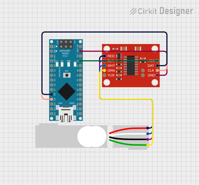
Pin Configuration and Descriptions
The HX711 has 16 pins, but only a subset is typically used in most applications. Below is the pin configuration:
| Pin | Name | Description |
|---|---|---|
| 1 | VCC | Power supply input (2.6V to 5.5V). |
| 2 | VFB | Feedback voltage for internal regulator (usually connected to VCC). |
| 3 | BASE | Base voltage for internal regulator (usually connected to ground). |
| 4 | AVDD | Analog power supply (connected to VCC). |
| 5 | AGND | Analog ground. |
| 6 | AINP | Positive input for Channel A. |
| 7 | AINN | Negative input for Channel A. |
| 8 | AINB | Positive input for Channel B. |
| 9 | AINB | Negative input for Channel B. |
| 10 | DGND | Digital ground. |
| 11 | PD_SCK | Power-down and serial clock input. Used for data retrieval and power control. |
| 12 | DOUT | Serial data output. |
| 13-16 | NC | Not connected. |
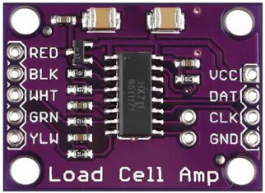
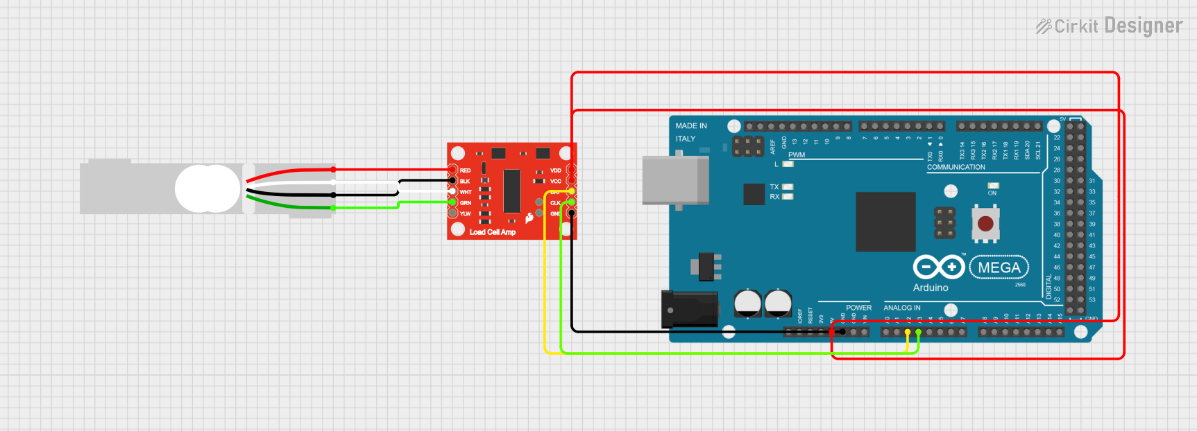
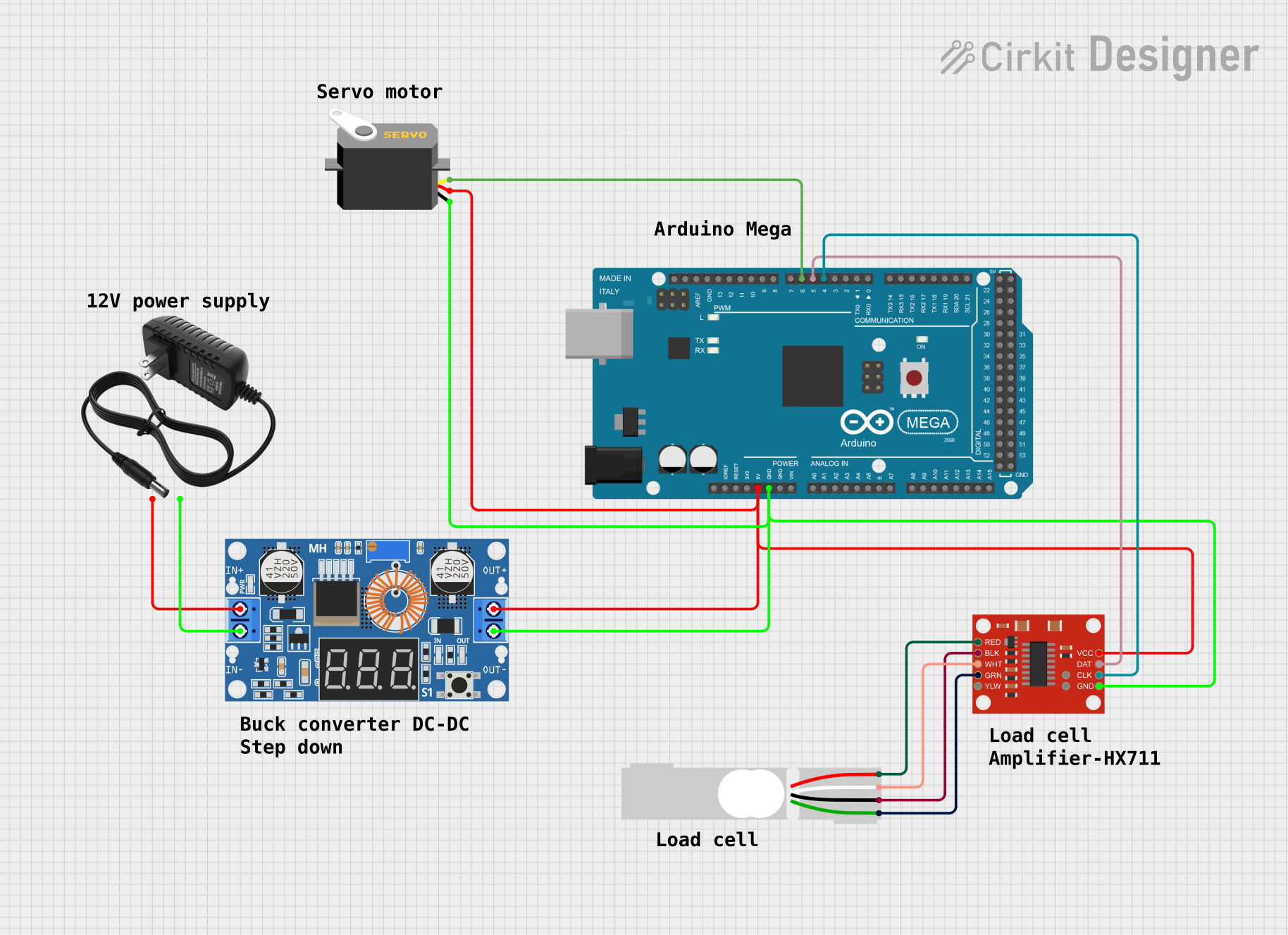
Usage Instructions
How to Use the HX711 in a Circuit
- Connect the Load Cell:
- Connect the load cell's positive and negative signal wires to the HX711's
AINPandAINNpins for Channel A. - If using Channel B, connect the load cell to
AINBpins.
- Connect the load cell's positive and negative signal wires to the HX711's
- Power the HX711:
- Provide a stable power supply (2.6V to 5.5V) to the
VCCpin. - Connect
AGNDandDGNDto the ground of your circuit.
- Provide a stable power supply (2.6V to 5.5V) to the
- Connect to a Microcontroller:
- Connect the
DOUTpin to a digital input pin on your microcontroller. - Connect the
PD_SCKpin to a digital output pin on your microcontroller.
- Connect the
- Set the Gain:
- The gain is set by the number of clock pulses sent to the
PD_SCKpin during data retrieval:- 25 pulses: Channel A, gain 128 (default).
- 27 pulses: Channel A, gain 64.
- 26 pulses: Channel B, gain 32.
- The gain is set by the number of clock pulses sent to the
Important Considerations and Best Practices
- Use a stable power supply to minimize noise and improve measurement accuracy.
- Place decoupling capacitors (e.g., 0.1µF) near the power pins to reduce power supply noise.
- Shield the load cell wires to prevent interference from external noise sources.
- Calibrate the system to ensure accurate weight measurements.
- Avoid exceeding the input voltage range of the load cell to prevent damage to the HX711.
Example Code for Arduino UNO
Below is an example of how to interface the HX711 with an Arduino UNO to read weight data:
#include "HX711.h" // Include the HX711 library

// Define HX711 pins
#define DOUT 3  // Data output pin connected to Arduino pin 3
#define SCK 2   // Serial clock pin connected to Arduino pin 2

HX711 scale; // Create an instance of the HX711 class

void setup() {
  Serial.begin(9600); // Initialize serial communication
  scale.begin(DOUT, SCK); // Initialize the HX711 with the defined pins
  scale.set_scale(); // Set the scale factor (calibration required)
  scale.tare(); // Reset the scale to zero
  Serial.println("HX711 initialized. Place weight on the scale.");
}

void loop() {
  if (scale.is_ready()) { // Check if the HX711 is ready
    long reading = scale.get_units(); // Get the weight in units
    Serial.print("Weight: ");
    Serial.print(reading);
    Serial.println(" units");
  } else {
    Serial.println("HX711 not ready. Check connections.");
  }
  delay(500); // Wait for 500ms before the next reading
}
Note: The HX711.h library must be installed in your Arduino IDE. You can install it via the Library Manager.
Troubleshooting and FAQs
Common Issues and Solutions
No Data Output:
- Cause: Incorrect wiring or loose connections.
- Solution: Double-check all connections, especially
DOUTandPD_SCK.
Unstable Readings:
- Cause: Noise or unstable power supply.
- Solution: Use a stable power source and add decoupling capacitors near the HX711.
Incorrect Weight Measurements:
- Cause: Improper calibration.
- Solution: Perform a proper calibration using known weights and adjust the scale factor.
HX711 Not Responding:
- Cause: Microcontroller not communicating with the HX711.
- Solution: Verify that the
PD_SCKandDOUTpins are correctly connected and configured in the code.
FAQs
Q: Can I use the HX711 with a 3.3V microcontroller?
- A: Yes, the HX711 operates at 2.6V to 5.5V, making it compatible with 3.3V systems.
Q: How do I calibrate the HX711?
- A: Use a known weight to determine the scale factor. Adjust the scale factor in the code using the
set_scale()function.
- A: Use a known weight to determine the scale factor. Adjust the scale factor in the code using the
Q: Can I use both channels (A and B) simultaneously?
- A: Yes, but you must switch between channels in the code by sending the appropriate number of clock pulses to
PD_SCK.
- A: Yes, but you must switch between channels in the code by sending the appropriate number of clock pulses to
Q: What is the maximum weight the HX711 can measure?
- A: The maximum weight depends on the load cell used. The HX711 itself does not impose a weight limit.