How to Use Pytrack v1.1: Examples, Pinouts, and Specs
Introduction
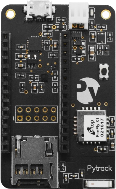
The Pytrack v1.1, manufactured by Pycom, is a versatile GPS and LoRaWAN tracker designed for Internet of Things (IoT) applications. It features low power consumption, high precision, and seamless compatibility with Pycom development boards and other microcontrollers. The Pytrack v1.1 is equipped with a GPS module, accelerometer, and a microcontroller interface, making it ideal for location tracking, motion detection, and IoT-based asset management.
Explore Projects Built with Pytrack v1.1
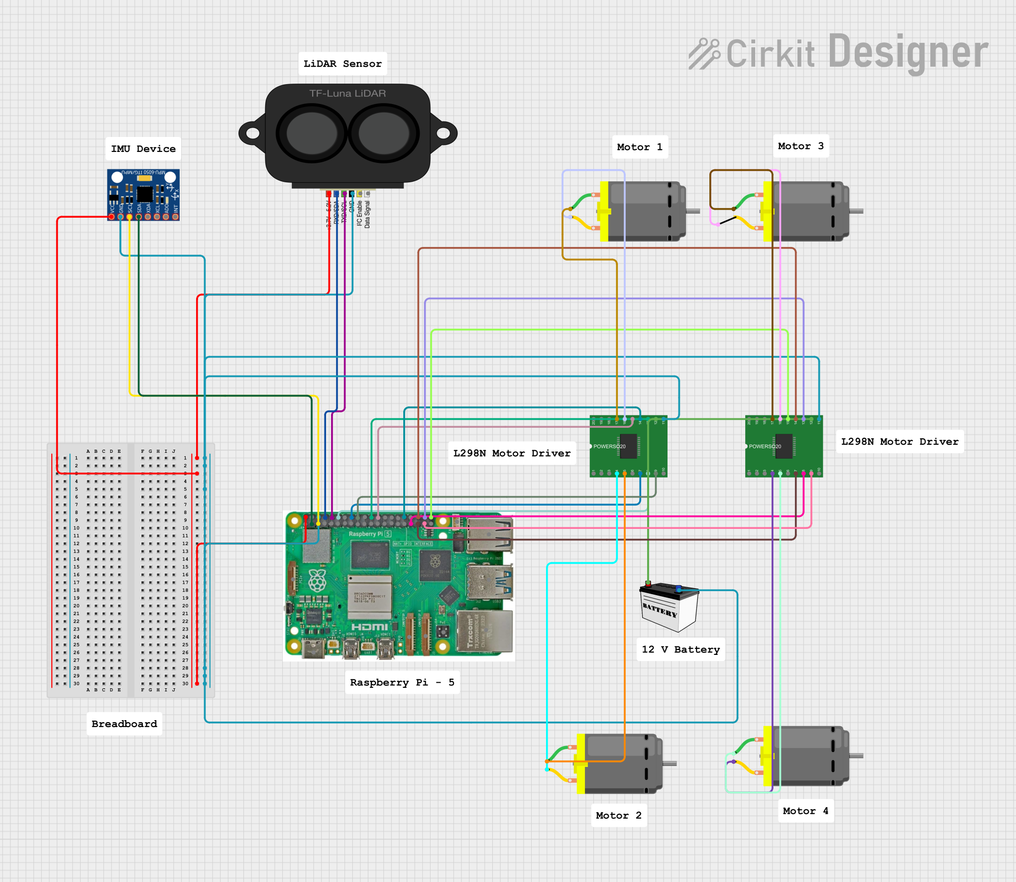

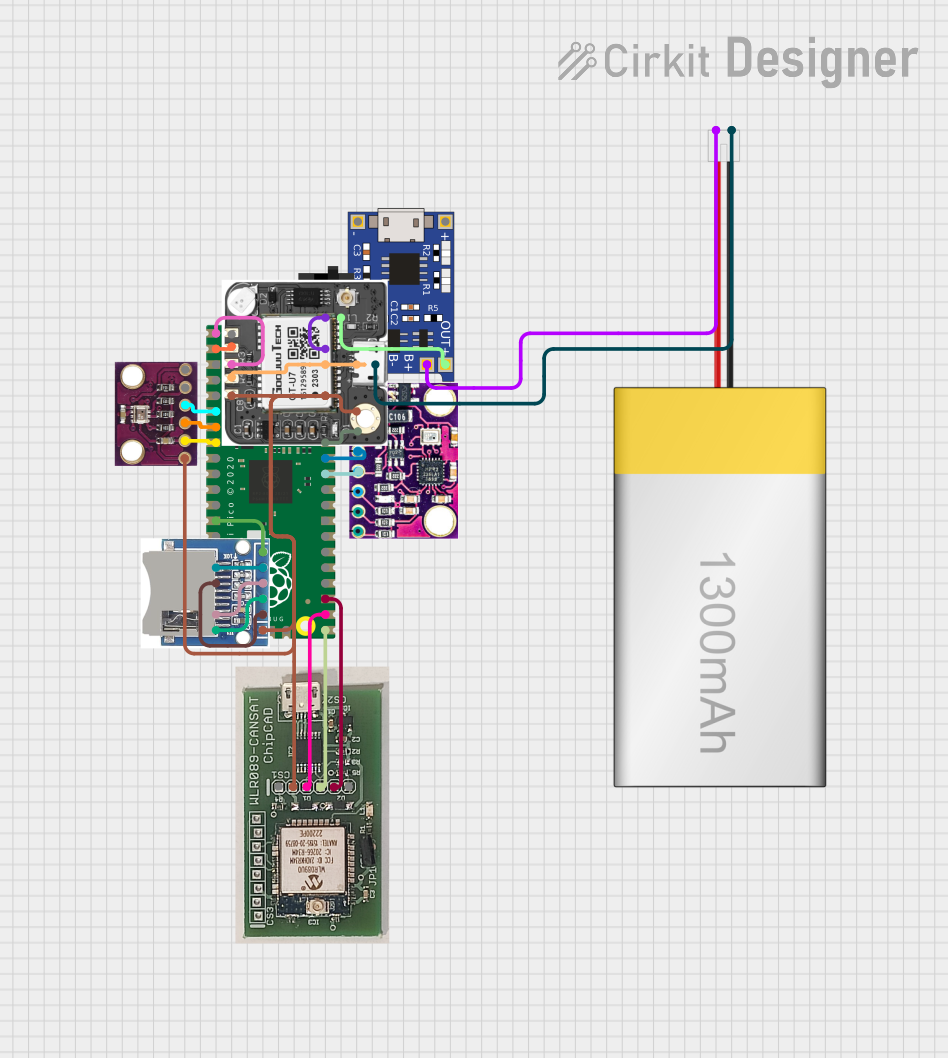

Explore Projects Built with Pytrack v1.1
Common Applications and Use Cases
- GPS-based location tracking for IoT devices
- Asset tracking and fleet management
- Motion detection and activity monitoring
- Low-power IoT applications requiring geolocation
- Integration with Pycom boards for rapid prototyping
Technical Specifications
Key Technical Details
| Parameter | Specification |
|---|---|
| Manufacturer | Pycom |
| Part ID | Pytrack v1.1 |
| GPS Module | Quectel L76-L |
| Accelerometer | LIS2HH12 (3-axis accelerometer) |
| Interface | I2C, UART |
| Power Supply Voltage | 3.3V to 5.5V |
| Operating Temperature | -40°C to +85°C |
| Dimensions | 55mm x 35mm |
| Compatibility | Pycom boards (e.g., LoPy, WiPy, etc.) |
Pin Configuration and Descriptions
The Pytrack v1.1 features a micro-USB port for power and communication, as well as a 16-pin header for interfacing with Pycom development boards or other microcontrollers.
| Pin Number | Pin Name | Description |
|---|---|---|
| 1 | 3V3 | 3.3V Power Supply |
| 2 | GND | Ground |
| 3 | SDA | I2C Data Line |
| 4 | SCL | I2C Clock Line |
| 5 | TX | UART Transmit |
| 6 | RX | UART Receive |
| 7 | RST | Reset |
| 8 | PWR_EN | Power Enable |
| 9-16 | Reserved | Reserved for Pycom board connections |
Usage Instructions
How to Use the Pytrack v1.1 in a Circuit
Powering the Pytrack v1.1:
Connect the Pytrack to a 3.3V or 5V power source via the micro-USB port or the 3V3 pin. Ensure the ground (GND) is connected to the circuit's ground.Interfacing with a Microcontroller:
- Use the I2C pins (SDA and SCL) to communicate with the accelerometer and other onboard sensors.
- Use the UART pins (TX and RX) to interface with the GPS module.
Connecting to a Pycom Board:
- Align the Pycom development board (e.g., LoPy, WiPy) with the Pytrack's 16-pin header.
- Ensure proper orientation to avoid damaging the board.
Programming the Pytrack:
- Install the Pycom firmware and libraries for the Pytrack.
- Use the Pycom Pymakr plugin with an IDE like Visual Studio Code or Atom to write and upload code.
Important Considerations and Best Practices
- Power Supply: Ensure a stable power supply to avoid erratic behavior of the GPS module and accelerometer.
- Antenna Placement: For optimal GPS performance, place the Pytrack in an open area with minimal obstructions.
- Firmware Updates: Regularly update the Pycom firmware to ensure compatibility and access to the latest features.
- Low Power Mode: Utilize the low-power features of the Pytrack for battery-powered applications.
Example Code for Arduino UNO
The Pytrack v1.1 is typically used with Pycom boards, but it can also be interfaced with an Arduino UNO using I2C. Below is an example code snippet to read data from the accelerometer:
#include <Wire.h>

// I2C address of the LIS2HH12 accelerometer
#define ACCEL_I2C_ADDR 0x1D

void setup() {
  Wire.begin(); // Initialize I2C communication
  Serial.begin(9600); // Initialize serial communication

  // Configure the accelerometer
  Wire.beginTransmission(ACCEL_I2C_ADDR);
  Wire.write(0x20); // CTRL_REG1: Enable accelerometer
  Wire.write(0x57); // Set data rate to 100 Hz, enable all axes
  Wire.endTransmission();

  Serial.println("Pytrack Accelerometer Initialized");
}

void loop() {
  int16_t x, y, z;

  // Request accelerometer data
  Wire.beginTransmission(ACCEL_I2C_ADDR);
  Wire.write(0x28 | 0x80); // OUT_X_L register with auto-increment
  Wire.endTransmission();
  Wire.requestFrom(ACCEL_I2C_ADDR, 6);

  // Read X, Y, Z axis data
  if (Wire.available() == 6) {
    x = Wire.read() | (Wire.read() << 8);
    y = Wire.read() | (Wire.read() << 8);
    z = Wire.read() | (Wire.read() << 8);
  }

  // Print accelerometer data
  Serial.print("X: "); Serial.print(x);
  Serial.print(" Y: "); Serial.print(y);
  Serial.print(" Z: "); Serial.println(z);

  delay(500); // Delay for readability
}
Troubleshooting and FAQs
Common Issues and Solutions
Pytrack Not Powering On:
- Ensure the power supply voltage is within the 3.3V to 5.5V range.
- Check the USB cable or power connections for faults.
GPS Not Acquiring Signal:
- Verify that the GPS antenna is properly connected and placed in an open area.
- Allow sufficient time for the GPS module to acquire a signal (cold start may take a few minutes).
I2C Communication Fails:
- Confirm the correct I2C address (default: 0x1D for the accelerometer).
- Check the SDA and SCL connections for continuity.
Pycom Board Not Detected:
- Ensure the Pycom board is properly seated on the Pytrack header.
- Update the Pycom firmware and libraries.
FAQs
Q: Can the Pytrack v1.1 be used with non-Pycom microcontrollers?
A: Yes, the Pytrack can be interfaced with other microcontrollers like Arduino or Raspberry Pi using I2C or UART.
Q: How do I update the Pytrack firmware?
A: Use the Pycom Firmware Update Tool, available on the Pycom website, to update the firmware.
Q: What is the typical power consumption of the Pytrack?
A: The Pytrack consumes approximately 20-30mA during normal operation, depending on the active modules.
Q: Can I use the Pytrack for outdoor applications?
A: Yes, but ensure the device is housed in a weatherproof enclosure for protection.