Cirkit Designer Logo
Cirkit Designer
Your all-in-one circuit design IDE
Home / 
Component Documentation

How to Use Optical Sensor: Examples, Pinouts, and Specs

Image of Optical Sensor
Cirkit Designer LogoDesign with Optical Sensor in Cirkit Designer

Introduction

An optical sensor is a device that detects light and converts it into an electrical signal. It is widely used in various applications, including cameras, light meters, automatic lighting systems, and industrial automation. Optical sensors are essential in systems that require light detection for measurement, control, or triggering actions. They are available in different types, such as photodiodes, phototransistors, and light-dependent resistors (LDRs), each suited for specific use cases.

Common applications of optical sensors include:

  • Ambient light detection in smartphones and displays
  • Proximity sensing in touchless interfaces
  • Object detection in robotics and automation
  • Light intensity measurement in scientific instruments
  • Security systems, such as motion detection

Explore Projects Built with Optical Sensor

Use Cirkit Designer to design, explore, and prototype these projects online. Some projects support real-time simulation. Click "Open Project" to start designing instantly!
ESP32-Based Eye Pressure Monitor with OLED Display and Multiple Sensors
Image of test4: A project utilizing Optical Sensor in a practical application
This circuit is designed to monitor eye pressure and deformation using a photodiode, a TCRT 5000 IR sensor, and a VL53L0X time-of-flight distance sensor. The ESP32 microcontroller reads sensor data, processes it to determine eye pressure status, and displays the results on a 0.96" OLED screen. It includes safety features, sensor calibration, and the ability to display sensor values and eye pressure status in real-time.
Cirkit Designer LogoOpen Project in Cirkit Designer
Arduino UNO and AS7262 Color Change Detection System with Bluetooth and OLED Display
Image of CAR project: A project utilizing Optical Sensor in a practical application
This circuit is designed to detect color changes in a solution using a spectral sensor, time the change, provide a sound cue via a piezo buzzer, and send the timing data to a computer via a Bluetooth module. The Arduino UNO microcontroller coordinates the sensor readings, timing, and communication, while an OLED display and NeoPixel ring provide visual feedback.
Cirkit Designer LogoOpen Project in Cirkit Designer
Arduino Mega 2560-Based Sensor Data Logger with ESP32-CAM and LCD Interface
Image of DA_Schema: A project utilizing Optical Sensor in a practical application
This is a multifunctional sensor system with visual feedback and control interfaces. It utilizes an Arduino Mega 2560 to process data from an accelerometer, ultrasonic sensor, and camera module, and displays information on an LCD screen. User inputs can be provided through toggle and DIP switches, while LEDs indicate system status.
Cirkit Designer LogoOpen Project in Cirkit Designer
Arduino Nano Controlled Optical Encoder with I2C LCD Display
Image of G7_DISTANCE_CALCULATOR: A project utilizing Optical Sensor in a practical application
This circuit features an Arduino Nano microcontroller interfaced with an Optical Encoder Sensor Module and an I2C LCD 16x2 Screen. The encoder module is connected to the Arduino's digital pin D2 for signal input, while the LCD screen is connected via I2C protocol to pins A4 (SDA) and A5 (SCL) for data display. Power is managed through a 18650 Li-Ion battery connected via a rocker switch to the Arduino's VIN pin, with common ground and 5V connections distributed among the components.
Cirkit Designer LogoOpen Project in Cirkit Designer

Explore Projects Built with Optical Sensor

Use Cirkit Designer to design, explore, and prototype these projects online. Some projects support real-time simulation. Click "Open Project" to start designing instantly!
Image of test4: A project utilizing Optical Sensor in a practical application
ESP32-Based Eye Pressure Monitor with OLED Display and Multiple Sensors
This circuit is designed to monitor eye pressure and deformation using a photodiode, a TCRT 5000 IR sensor, and a VL53L0X time-of-flight distance sensor. The ESP32 microcontroller reads sensor data, processes it to determine eye pressure status, and displays the results on a 0.96" OLED screen. It includes safety features, sensor calibration, and the ability to display sensor values and eye pressure status in real-time.
Cirkit Designer LogoOpen Project in Cirkit Designer
Image of CAR project: A project utilizing Optical Sensor in a practical application
Arduino UNO and AS7262 Color Change Detection System with Bluetooth and OLED Display
This circuit is designed to detect color changes in a solution using a spectral sensor, time the change, provide a sound cue via a piezo buzzer, and send the timing data to a computer via a Bluetooth module. The Arduino UNO microcontroller coordinates the sensor readings, timing, and communication, while an OLED display and NeoPixel ring provide visual feedback.
Cirkit Designer LogoOpen Project in Cirkit Designer
Image of DA_Schema: A project utilizing Optical Sensor in a practical application
Arduino Mega 2560-Based Sensor Data Logger with ESP32-CAM and LCD Interface
This is a multifunctional sensor system with visual feedback and control interfaces. It utilizes an Arduino Mega 2560 to process data from an accelerometer, ultrasonic sensor, and camera module, and displays information on an LCD screen. User inputs can be provided through toggle and DIP switches, while LEDs indicate system status.
Cirkit Designer LogoOpen Project in Cirkit Designer
Image of G7_DISTANCE_CALCULATOR: A project utilizing Optical Sensor in a practical application
Arduino Nano Controlled Optical Encoder with I2C LCD Display
This circuit features an Arduino Nano microcontroller interfaced with an Optical Encoder Sensor Module and an I2C LCD 16x2 Screen. The encoder module is connected to the Arduino's digital pin D2 for signal input, while the LCD screen is connected via I2C protocol to pins A4 (SDA) and A5 (SCL) for data display. Power is managed through a 18650 Li-Ion battery connected via a rocker switch to the Arduino's VIN pin, with common ground and 5V connections distributed among the components.
Cirkit Designer LogoOpen Project in Cirkit Designer

Technical Specifications

The technical specifications of an optical sensor can vary depending on the type and model. Below is a general overview of key specifications for a typical optical sensor:

Parameter Value
Operating Voltage 3.3V to 5V
Operating Current 10mA to 20mA
Light Sensitivity Range 400nm to 700nm (visible spectrum)
Response Time 10µs to 1ms
Output Type Analog or Digital
Operating Temperature -20°C to 70°C

Pin Configuration and Descriptions

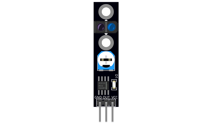
The pin configuration of an optical sensor depends on its type. Below is an example for a 3-pin phototransistor-based optical sensor:

Pin Name Description
1 VCC Power supply pin (3.3V or 5V)
2 GND Ground connection
3 OUT Output pin (provides an analog or digital signal)

For a light-dependent resistor (LDR), the sensor typically has two terminals that are connected in a voltage divider circuit.

Usage Instructions

How to Use the Component in a Circuit

  1. Power the Sensor: Connect the VCC pin to a 3.3V or 5V power supply and the GND pin to the ground.
  2. Read the Output: Connect the OUT pin to an analog or digital input pin of a microcontroller (e.g., Arduino UNO) to read the sensor's output.
  3. Voltage Divider for LDR: If using an LDR, connect it in series with a fixed resistor to form a voltage divider. The junction between the LDR and the resistor provides the output voltage.

Example Circuit with Arduino UNO

Below is an example of connecting an optical sensor to an Arduino UNO:

Circuit Connections

  • Connect the VCC pin of the optical sensor to the 5V pin on the Arduino.
  • Connect the GND pin of the sensor to the GND pin on the Arduino.
  • Connect the OUT pin of the sensor to an analog input pin (e.g., A0) on the Arduino.

Arduino Code

// Optical Sensor Example with Arduino UNO
// Reads the sensor's output and prints the light intensity to the Serial Monitor

const int sensorPin = A0; // Analog pin connected to the sensor's OUT pin
int sensorValue = 0;      // Variable to store the sensor reading

void setup() {
  Serial.begin(9600); // Initialize serial communication at 9600 baud
}

void loop() {
  sensorValue = analogRead(sensorPin); // Read the sensor's analog output
  Serial.print("Light Intensity: ");
  Serial.println(sensorValue); // Print the sensor value to the Serial Monitor
  delay(500); // Wait for 500ms before the next reading
}

Important Considerations and Best Practices

  • Avoid Direct Sunlight: Prolonged exposure to direct sunlight can damage the sensor or affect its accuracy.
  • Use Proper Pull-Up Resistors: For digital output sensors, ensure the correct pull-up resistor is used if required.
  • Shield from Interference: Place the sensor away from sources of electrical noise or strong light interference.
  • Calibrate for Accuracy: If precise measurements are required, calibrate the sensor for your specific application.

Troubleshooting and FAQs

Common Issues and Solutions

  1. No Output Signal:

    • Check the power supply connections (VCC and GND).
    • Ensure the sensor is not damaged or exposed to extreme conditions.
  2. Inconsistent Readings:

    • Verify that the sensor is not exposed to fluctuating light sources.
    • Use a capacitor across the power supply pins to filter noise.
  3. Low Sensitivity:

    • Ensure the sensor is clean and free from dust or debris.
    • Check if the sensor is operating within its specified light sensitivity range.
  4. Arduino Not Detecting Sensor Output:

    • Confirm that the correct pin is used in the code.
    • Check the wiring and ensure the sensor's output is connected to the correct Arduino pin.

FAQs

Q: Can I use an optical sensor in outdoor applications?
A: Yes, but ensure the sensor is protected from direct sunlight, rain, and extreme temperatures. Use an appropriate enclosure if necessary.

Q: How do I increase the sensitivity of the sensor?
A: You can adjust the circuit design, such as using a higher-value resistor in the voltage divider for an LDR or amplifying the output signal with an operational amplifier.

Q: Can I use multiple optical sensors in the same circuit?
A: Yes, you can connect multiple sensors to different input pins of a microcontroller. Ensure each sensor has its own power and ground connections.

By following this documentation, you can effectively integrate and troubleshoot an optical sensor in your projects.