
How to Use mpu 6050: Examples, Pinouts, and Specs
 Design with mpu 6050 in Cirkit Designer
Introduction
The MPU 6050, manufactured by ESP32 under the part ID "ESP32 Mikrokontoler," is a 6-axis motion tracking device. It integrates a 3-axis gyroscope and a 3-axis accelerometer on a single chip, enabling precise measurement of orientation, acceleration, and angular velocity. This compact and versatile sensor is widely used in applications such as robotics, drones, gaming devices, and wearable technology.
Explore Projects Built with mpu 6050
 Open Project in Cirkit Designer
 Open Project in Cirkit Designer
 Open Project in Cirkit Designer
 Open Project in Cirkit Designer
Explore Projects Built with mpu 6050
Open Project in Cirkit DesignerOpen Project in Cirkit DesignerOpen Project in Cirkit DesignerOpen Project in Cirkit DesignerCommon Applications:
- Robotics: For balancing robots and motion control.
- Drones: To measure orientation and stabilize flight.
- Gaming Devices: For motion-based controls.
- Wearable Devices: To track movement and activity.
- IoT Projects: For motion sensing in smart devices.
Technical Specifications
The MPU 6050 is a high-performance sensor with the following key specifications:
| Parameter | Value |
|---|---|
| Supply Voltage | 2.375V to 3.46V |
| Operating Current | 3.9 mA (typical) |
| Gyroscope Range | ±250, ±500, ±1000, ±2000 °/s |
| Accelerometer Range | ±2g, ±4g, ±8g, ±16g |
| Communication Protocol | I2C (up to 400kHz) or SPI |
| Operating Temperature | -40°C to +85°C |
| Package Type | QFN-24 |
Pin Configuration and Descriptions
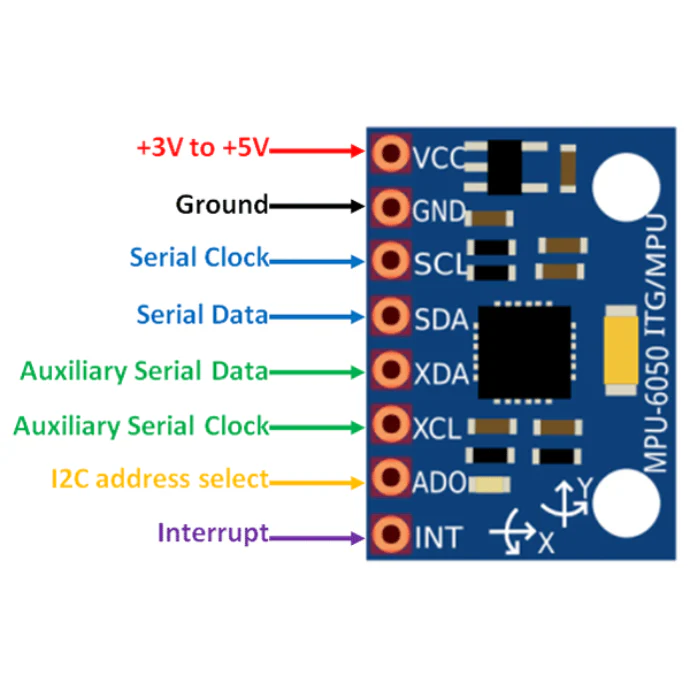
The MPU 6050 has 8 pins, as described in the table below:
| Pin Name | Pin Number | Description |
|---|---|---|
| VCC | 1 | Power supply input (2.375V to 3.46V). |
| GND | 2 | Ground connection. |
| SCL | 3 | I2C clock line. |
| SDA | 4 | I2C data line. |
| AD0 | 5 | I2C address select (connect to GND or VCC). |
| INT | 6 | Interrupt output for motion detection. |
| FSYNC | 7 | Frame synchronization input (optional). |
| RES | 8 | Reserved (leave unconnected). |
Usage Instructions
Connecting the MPU 6050 to an Arduino UNO
To use the MPU 6050 with an Arduino UNO, follow these steps:
Wiring:
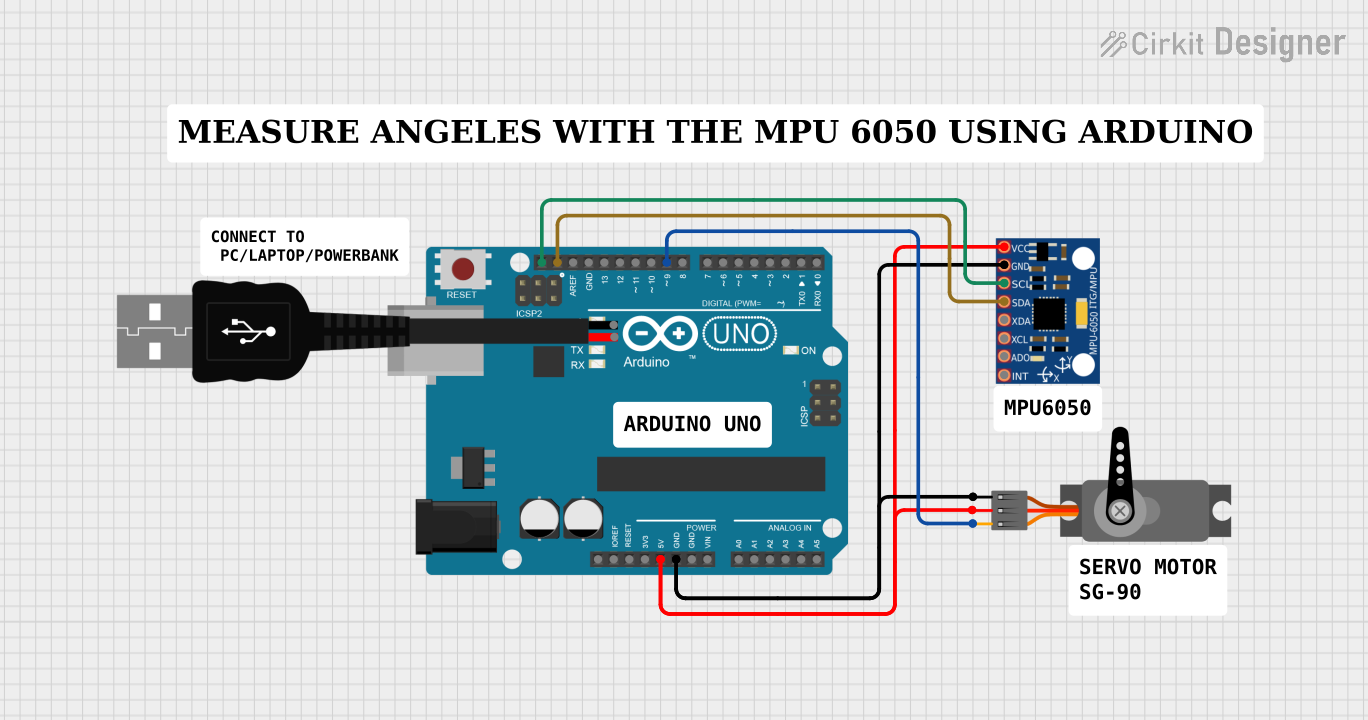
- Connect the VCC pin of the MPU 6050 to the 3.3V pin on the Arduino.
- Connect the GND pin to the Arduino's GND.
- Connect the SCL pin to the Arduino's A5 pin (I2C clock line).
- Connect the SDA pin to the Arduino's A4 pin (I2C data line).
- Optionally, connect the INT pin to a digital pin on the Arduino for motion interrupts.
Install Required Libraries:
- Install the
Wire.hlibrary (pre-installed with Arduino IDE). - Install the
MPU6050library from the Arduino Library Manager.
- Install the
Sample Code: Use the following code to read accelerometer and gyroscope data:
#include <Wire.h>
#include <MPU6050.h>

MPU6050 mpu;

void setup() {
  Serial.begin(9600); // Initialize serial communication at 9600 baud
  Wire.begin();       // Initialize I2C communication

  // Initialize the MPU 6050
  if (!mpu.begin(MPU6050_SCALE_2000DPS, MPU6050_RANGE_2G)) {
    Serial.println("Could not find a valid MPU6050 sensor!");
    while (1); // Halt execution if sensor initialization fails
  }

  Serial.println("MPU6050 initialized successfully!");
}

void loop() {
  Vector rawAccel = mpu.readRawAccel(); // Read raw accelerometer data
  Vector rawGyro = mpu.readRawGyro();   // Read raw gyroscope data

  // Print accelerometer data
  Serial.print("Accel X: "); Serial.print(rawAccel.XAxis);
  Serial.print(" | Y: "); Serial.print(rawAccel.YAxis);
  Serial.print(" | Z: "); Serial.println(rawAccel.ZAxis);

  // Print gyroscope data
  Serial.print("Gyro X: "); Serial.print(rawGyro.XAxis);
  Serial.print(" | Y: "); Serial.print(rawGyro.YAxis);
  Serial.print(" | Z: "); Serial.println(rawGyro.ZAxis);

  delay(500); // Wait for 500ms before the next reading
}
Important Considerations:
- Power Supply: Ensure the MPU 6050 is powered within its specified voltage range (2.375V to 3.46V). Using 5V directly may damage the sensor.
- Pull-Up Resistors: The I2C lines (SCL and SDA) may require external pull-up resistors (typically 4.7kΩ) if not already present on the breakout board.
- I2C Address: The default I2C address is
0x68. If the AD0 pin is connected to VCC, the address changes to0x69.
Troubleshooting and FAQs
Common Issues:
No Data from the Sensor:
- Cause: Incorrect wiring or I2C address mismatch.
- Solution: Double-check the connections and ensure the correct I2C address is used in the code.
Unstable or Noisy Readings:
- Cause: Electrical noise or improper grounding.
- Solution: Use shorter wires and ensure a solid ground connection.
Sensor Not Detected:
- Cause: Faulty sensor or incorrect initialization.
- Solution: Verify the sensor's power supply and try reinitializing it in the code.
FAQs:
Q: Can the MPU 6050 be used with 5V logic?
- A: The MPU 6050 operates at 3.3V. If using a 5V microcontroller, use a logic level shifter for the I2C lines.
Q: How do I calibrate the MPU 6050?
- A: Calibration involves reading the sensor's offsets when it is stationary and subtracting these offsets from subsequent readings.
Q: Can I use SPI instead of I2C?
- A: The MPU 6050 primarily supports I2C. SPI is not commonly used with this sensor.
By following this documentation, you can effectively integrate the MPU 6050 into your projects and troubleshoot common issues.