How to Use Adafruit HUZZAH32 ESP32 Feather: Examples, Pinouts, and Specs
Introduction
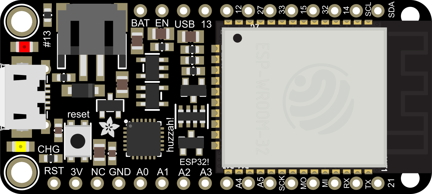
The Adafruit HUZZAH32 ESP32 Feather is a compact development board based on the popular ESP32 microcontroller. This board is part of the Feather ecosystem, which is a collection of development boards with a standardized form factor and pinout, designed by Adafruit Industries. The HUZZAH32 is specifically tailored for Internet of Things (IoT) projects, wireless connectivity, and rapid prototyping. It offers a rich set of features including Wi-Fi and Bluetooth connectivity, a wide range of GPIOs, and compatibility with a multitude of sensors and actuators.
Explore Projects Built with Adafruit HUZZAH32 ESP32 Feather
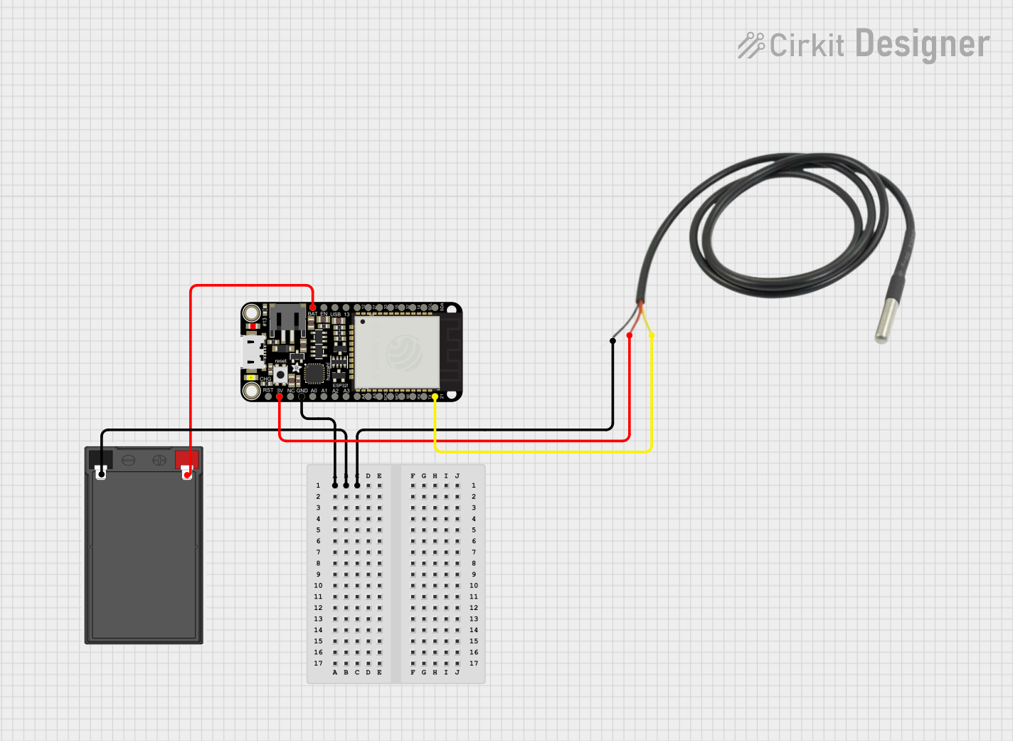
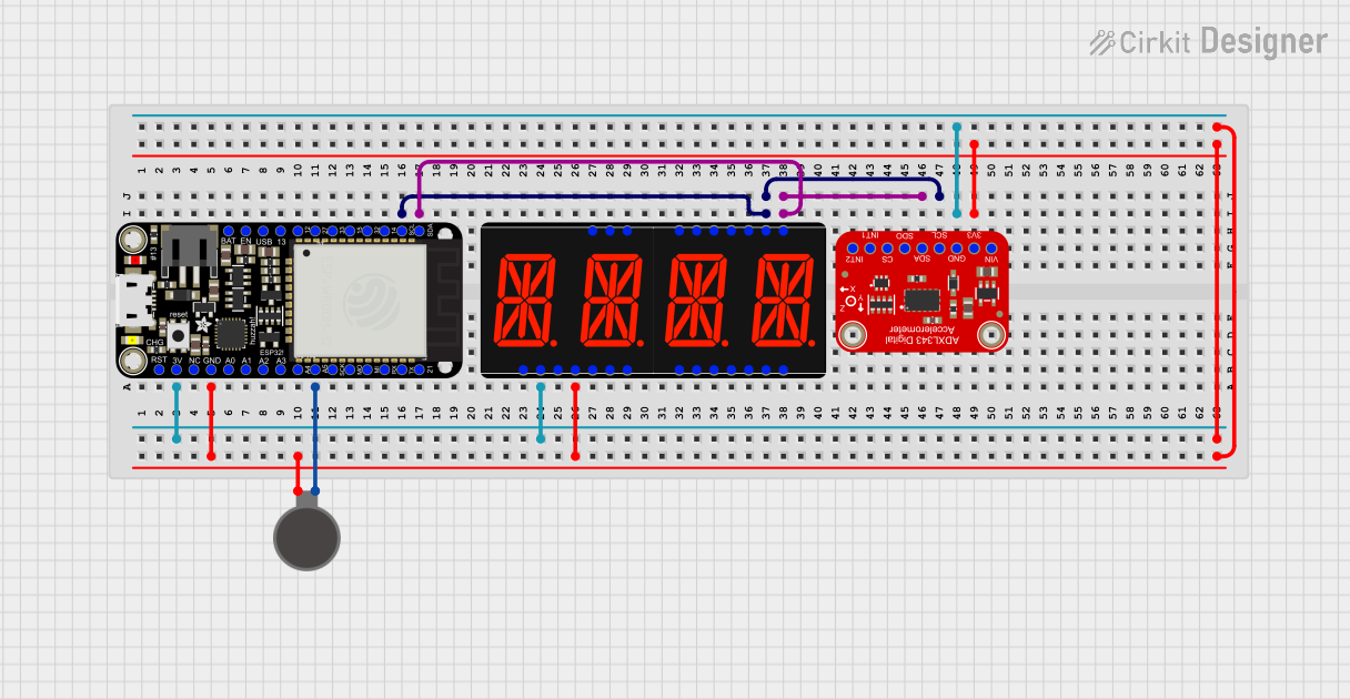
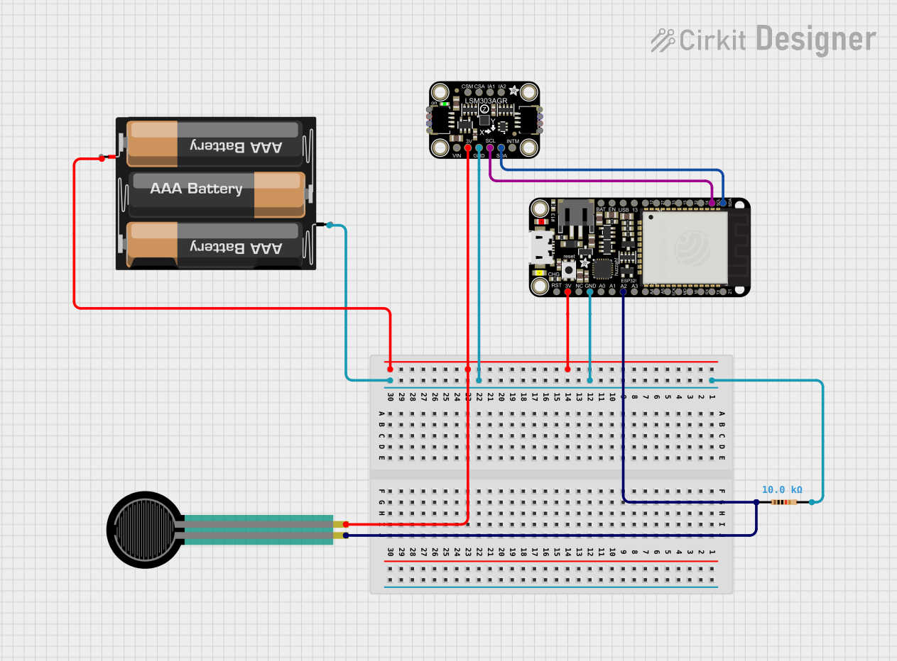
Explore Projects Built with Adafruit HUZZAH32 ESP32 Feather
Common Applications and Use Cases
- IoT devices and sensors
- Wireless data loggers
- Home automation systems
- Wearable electronics
- Prototyping for embedded systems
Technical Specifications
Key Technical Details
- Microcontroller: ESP32 (dual-core, 240 MHz)
- Operating Voltage: 3.3V
- Input Voltage: 3.4V to 6V via USB or battery
- Digital I/O Pins: 25
- Analog Input Pins: 6 (12-bit ADC)
- Analog Output Pins: 2 (8-bit DAC)
- Flash Memory: 4 MB
- SRAM: 520 KB
- Wi-Fi: 802.11 b/g/n
- Bluetooth: Bluetooth 4.2 BR/EDR and BLE
- Dimensions: 51mm x 23mm x 8mm
Pin Configuration and Descriptions
| Pin Number | Function | Description |
|---|---|---|
| 1 | GND | Ground |
| 2 | 3V | 3.3V power supply |
| 3 | EN | Reset pin (active low) |
| 4 | 21 (SDA) | I2C Data |
| 5 | 22 (SCL) | I2C Clock |
| 6 | 23 | SPI MOSI (Master Out Slave In) |
| 7 | 24 | SPI MISO (Master In Slave Out) |
| 8 | 25 | SPI CLK (Clock) |
| 9 | A0 | Analog input |
| ... | ... | ... |
| 28 | TXO | Serial Transmit |
| 29 | RXI | Serial Receive |
| 30 | A5 | Analog input (can also be used as a DAC output) |
Note: This is a partial list of pins for brevity. Please refer to the official datasheet for the full pinout.
Usage Instructions
How to Use the Component in a Circuit
Powering the Board:
- You can power the HUZZAH32 via the USB port or with an external battery.
- Ensure that the input voltage does not exceed the recommended 6V.
Programming the Board:
- Install the required CP2104 USB driver and the ESP32 Arduino core.
- Select the Adafruit ESP32 Feather board from the Arduino IDE.
- Connect the board to your computer using a micro USB cable.
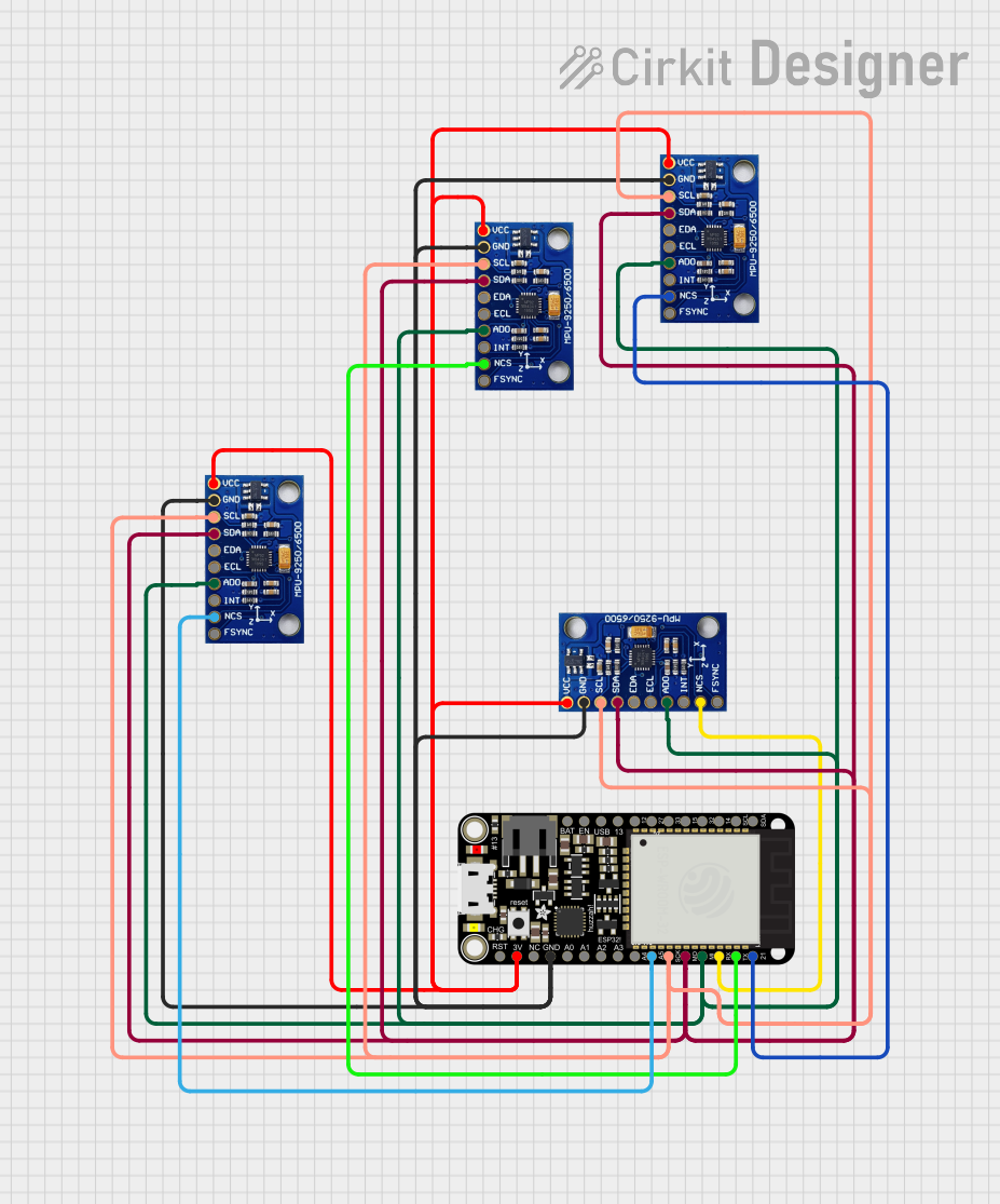
Connecting Peripherals:
- Use the pinout table to connect sensors, actuators, or other peripherals.
- Ensure that peripherals are compatible with the board's operating voltage.
Important Considerations and Best Practices
- Always disconnect the board from power sources before making or altering connections.
- Use a logic level converter if you need to interface with 5V components.
- Avoid drawing more current than the board's regulator can supply when connecting external components.
Troubleshooting and FAQs
Common Issues
- Board not recognized by the computer:
- Ensure the USB cable is properly connected and the CP2104 drivers are installed.
- Failure to connect to Wi-Fi:
- Check the SSID and password in your code. Ensure the Wi-Fi network is 2.4 GHz as the ESP32 does not support 5 GHz networks.
Solutions and Tips for Troubleshooting
- Board not responding:
- Press the reset button on the board. If that doesn't work, try re-flashing the board with a simple blink sketch to ensure it's working.
- Cannot upload sketches:
- Check the correct board and port are selected in the Arduino IDE. Make sure no other programs are using the COM port.
FAQs
- Q: Can I use the Arduino IDE to program the HUZZAH32?
- A: Yes, after installing the ESP32 Arduino core, you can use the Arduino IDE.
- Q: What is the maximum current draw from the 3.3V pin?
- A: The maximum current draw from the 3.3V pin should not exceed 500 mA.
Example Code for Arduino UNO
Here is a simple example of how to blink an LED connected to pin 13 on the HUZZAH32 using the Arduino IDE:
// Define the LED pin
const int ledPin = 13;

// the setup function runs once when you press reset or power the board
void setup() {
  // initialize digital pin ledPin as an output.
  pinMode(ledPin, OUTPUT);
}

// the loop function runs over and over again forever
void loop() {
  digitalWrite(ledPin, HIGH);   // turn the LED on (HIGH is the voltage level)
  delay(1000);                  // wait for a second
  digitalWrite(ledPin, LOW);    // turn the LED off by making the voltage LOW
  delay(1000);                  // wait for a second
}
Note: This code is for demonstration purposes and assumes an LED with an appropriate resistor is connected to pin 13.
Remember to wrap your code comments to limit line length to 80 characters, as shown above. This ensures readability and maintains a clean, professional appearance in your documentation.