Cirkit Designer Logo
Cirkit Designer
Your all-in-one circuit design IDE
Home / 
Component Documentation

How to Use boost converter MT3608: Examples, Pinouts, and Specs

Image of boost converter MT3608
Cirkit Designer LogoDesign with boost converter MT3608 in Cirkit Designer

Introduction

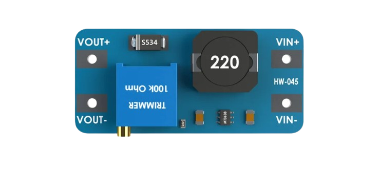
The MT3608 is a highly efficient, fixed frequency, step-up (boost) converter designed for a wide range of applications. It is capable of driving a 1.2A load with excellent line and load regulation. The device is suitable for battery-powered devices, portable electronics, and any system requiring a higher voltage output from a lower voltage source.

Explore Projects Built with boost converter MT3608

Use Cirkit Designer to design, explore, and prototype these projects online. Some projects support real-time simulation. Click "Open Project" to start designing instantly!
Voltage Regulation System with MT3608 Boost and LM2596 Buck Converters
Image of solar system router ups: A project utilizing boost converter MT3608 in a practical application
This circuit consists of two MT3608 boost converters and an LM2596 step-down module, each connected to separate 12V power supplies. The MT3608 modules are configured to step up the voltage from their respective power supplies, while the LM2596 module steps down the voltage from a 12V battery. Diodes are used to ensure correct current flow direction, potentially for protection or isolation between different parts of the circuit.
Cirkit Designer LogoOpen Project in Cirkit Designer
Battery-Powered DC Motor Control with USB Charging and LED Indicator
Image of lumantas: A project utilizing boost converter MT3608 in a practical application
This circuit is designed to charge a Li-ion battery and power a DC motor and a 12V LED. The TP4056 module manages the battery charging process, while the PowerBoost 1000 and MT3608 boost converters step up the voltage to drive the motor and LED, respectively. Two rocker switches control the power flow to the LED and the charging circuit.
Cirkit Designer LogoOpen Project in Cirkit Designer
ESP32-Powered Obstacle Avoidance Robot with IR and Ultrasonic Sensors
Image of projcememek: A project utilizing boost converter MT3608 in a practical application
This circuit features a 18650 Li-Ion battery connected to a TP4056 charging module, which in turn is connected to an MT3608 boost converter to step up the voltage. The output of the MT3608 powers an ESP32 microcontroller, a TCRT 5000 IR sensor, an HC-SR04 ultrasonic sensor, and an MG996R servo motor. The ESP32 is configured to control the servo motor via GPIO 27 and to receive input signals from the IR sensor and ultrasonic sensor through GPIO 14 and GPIO 13, respectively.
Cirkit Designer LogoOpen Project in Cirkit Designer
Battery-Powered DC-DC Converter System for Multi-Voltage Power Distribution
Image of test 1 ih: A project utilizing boost converter MT3608 in a practical application
This circuit converts a 38.5V battery output to multiple lower voltage levels using a series of DC-DC converters and a power module. It includes an emergency stop switch for safety and distributes power to various components such as a relay module, USB ports, and a bus servo adaptor.
Cirkit Designer LogoOpen Project in Cirkit Designer

Explore Projects Built with boost converter MT3608

Use Cirkit Designer to design, explore, and prototype these projects online. Some projects support real-time simulation. Click "Open Project" to start designing instantly!
Image of solar system router ups: A project utilizing boost converter MT3608 in a practical application
Voltage Regulation System with MT3608 Boost and LM2596 Buck Converters
This circuit consists of two MT3608 boost converters and an LM2596 step-down module, each connected to separate 12V power supplies. The MT3608 modules are configured to step up the voltage from their respective power supplies, while the LM2596 module steps down the voltage from a 12V battery. Diodes are used to ensure correct current flow direction, potentially for protection or isolation between different parts of the circuit.
Cirkit Designer LogoOpen Project in Cirkit Designer
Image of lumantas: A project utilizing boost converter MT3608 in a practical application
Battery-Powered DC Motor Control with USB Charging and LED Indicator
This circuit is designed to charge a Li-ion battery and power a DC motor and a 12V LED. The TP4056 module manages the battery charging process, while the PowerBoost 1000 and MT3608 boost converters step up the voltage to drive the motor and LED, respectively. Two rocker switches control the power flow to the LED and the charging circuit.
Cirkit Designer LogoOpen Project in Cirkit Designer
Image of projcememek: A project utilizing boost converter MT3608 in a practical application
ESP32-Powered Obstacle Avoidance Robot with IR and Ultrasonic Sensors
This circuit features a 18650 Li-Ion battery connected to a TP4056 charging module, which in turn is connected to an MT3608 boost converter to step up the voltage. The output of the MT3608 powers an ESP32 microcontroller, a TCRT 5000 IR sensor, an HC-SR04 ultrasonic sensor, and an MG996R servo motor. The ESP32 is configured to control the servo motor via GPIO 27 and to receive input signals from the IR sensor and ultrasonic sensor through GPIO 14 and GPIO 13, respectively.
Cirkit Designer LogoOpen Project in Cirkit Designer
Image of test 1 ih: A project utilizing boost converter MT3608 in a practical application
Battery-Powered DC-DC Converter System for Multi-Voltage Power Distribution
This circuit converts a 38.5V battery output to multiple lower voltage levels using a series of DC-DC converters and a power module. It includes an emergency stop switch for safety and distributes power to various components such as a relay module, USB ports, and a bus servo adaptor.
Cirkit Designer LogoOpen Project in Cirkit Designer

Common Applications

  • Powering 5V or 12V devices from a single-cell lithium-ion battery
  • Supplying power to LED strings
  • Portable power banks
  • USB-powered devices requiring higher voltages

Technical Specifications

Key Technical Details

  • Input Voltage Range: 2V to 24V
  • Maximum Output Voltage: 28V
  • Switch Current Limit: 4A (typical)
  • Quiescent Current: 200µA
  • Efficiency: Up to 93%
  • Switching Frequency: 1.2MHz
  • Operating Temperature: -40°C to +85°C

Pin Configuration and Descriptions

Pin Number Name Description
1 GND Ground connection. Connect to the system ground plane.
2 EN Enable pin. Drive high to enable the converter, low to disable.
3 VIN Input voltage. Connect to the source of the DC voltage to be boosted.
4 SW Switch pin. Connects to the inductor, carrying the switching current.
5 FB Feedback pin. Connects to the voltage divider for output voltage regulation.
6 VOUT Output voltage. The boosted voltage is available at this pin.

Usage Instructions

How to Use the MT3608 in a Circuit

  1. Connecting Input Power:

    • Connect the source voltage to the VIN pin.
    • Connect the ground of the power source to the GND pin.
  2. Output Voltage Setup:

    • Attach a resistor divider from VOUT to FB to GND to set the desired output voltage.
    • The output voltage can be calculated using the formula: Vout = 0.6V * (1 + R1/R2), where 0.6V is the reference voltage.
  3. Inductor Selection:

    • Choose an inductor with a current rating above the maximum load current and a saturation current above the switch current limit.
  4. Capacitor Selection:

    • Use a good quality ceramic capacitor at the input and output for stability.
    • The input capacitor should be rated for at least the maximum input voltage.
    • The output capacitor should be rated for at least the maximum output voltage.
  5. Enable Pin:

    • To turn on the MT3608, apply a high logic level to the EN pin.
    • To turn off the MT3608, apply a low logic level to the EN pin.

Important Considerations and Best Practices

  • Ensure that the input voltage does not exceed the maximum rating of 24V.
  • Do not exceed the maximum output voltage of 28V.
  • The layout of the PCB should minimize the loop area formed by the input capacitor, the MT3608, and the inductor to reduce EMI.
  • Keep the feedback trace away from noisy components to avoid interference.
  • Use a heat sink if the converter is expected to handle loads near the upper limit of its capability.

Troubleshooting and FAQs

Common Issues

  • Output Voltage Not Regulated:

    • Check the resistor divider values connected to the FB pin.
    • Ensure that the feedback trace is not picking up noise.
  • Converter Not Starting:

    • Verify that the EN pin is being driven high.
    • Check for proper input voltage and connections.
  • Excessive Noise or Ripple:

    • Ensure that the input and output capacitors are of adequate value and quality.
    • Check the PCB layout for large loop areas that could be causing EMI.

FAQs

Q: Can the MT3608 be used to charge batteries? A: Yes, but an additional charge controller circuit is required to safely charge batteries.

Q: What is the maximum current the MT3608 can output? A: The MT3608 can drive a 1.2A load, but the actual current capability depends on input voltage, output voltage, and thermal conditions.

Q: How do I adjust the output voltage? A: The output voltage is set by a resistor divider connected to the FB pin. Adjust the resistor values according to the formula provided in the Usage Instructions.

Q: Is the MT3608 suitable for automotive applications? A: The MT3608 can be used in automotive applications, provided the input voltage range is within specification and proper thermal management is in place.

Example Arduino Connection

// Example code to control the MT3608 Boost Converter with an Arduino UNO

const int enablePin = 9; // Connect to the EN pin of the MT3608

void setup() {
  pinMode(enablePin, OUTPUT);
  digitalWrite(enablePin, LOW); // Start with the converter disabled
}

void loop() {
  // Enable the MT3608 for 5 seconds
  digitalWrite(enablePin, HIGH);
  delay(5000);
  
  // Disable the MT3608 for 5 seconds
  digitalWrite(enablePin, LOW);
  delay(5000);
}

Note: This code example simply turns the MT3608 on and off. For applications requiring variable output voltage control via the Arduino, additional circuitry and code would be necessary to adjust the feedback resistors or to use a digital potentiometer connected to the FB pin.