How to Use EVAL-ADM3068E: Examples, Pinouts, and Specs
Introduction
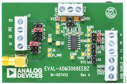
The EVAL-ADM3068E is an evaluation board designed by Analog Devices to demonstrate the performance and functionality of the ADM3068E, a high-speed, isolated RS-485 transceiver. This component is engineered for robust and reliable communication in industrial environments, offering integrated isolation to protect against electrical noise, surges, and ground potential differences. The evaluation board simplifies the testing and integration of the ADM3068E into various applications.
Explore Projects Built with EVAL-ADM3068E


Explore Projects Built with EVAL-ADM3068E
Common Applications and Use Cases
- Industrial automation and control systems
- Building automation (e.g., HVAC systems)
- Long-distance data communication
- Motor control and drive systems
- Isolated RS-485/RS-422 communication networks
Technical Specifications
Key Technical Details
- Transceiver Type: Isolated RS-485/RS-422
- Data Rate: Up to 25 Mbps
- Isolation Voltage: 2.5 kV RMS
- Supply Voltage:
- VDD1 (Primary Side): 3.0 V to 5.5 V
- VDD2 (Secondary Side): 3.0 V to 5.5 V
- Operating Temperature Range: -40°C to +125°C
- ESD Protection: ±15 kV (IEC 61000-4-2, contact discharge)
- Bus Capacitance: 12 pF (typical)
- Driver Output Voltage: ±1.5 V minimum (with 54 Ω load)
Pin Configuration and Descriptions
The EVAL-ADM3068E board provides access to the ADM3068E transceiver pins via test points and connectors. Below is the pin configuration for the ADM3068E IC:
| Pin Name | Pin Number | Description |
|---|---|---|
| VDD1 | 1 | Primary-side power supply (3.0 V to 5.5 V). |
| GND1 | 2 | Primary-side ground. |
| TXD | 3 | Transmit data input. |
| RXD | 4 | Receive data output. |
| DE | 5 | Driver enable input. High to enable driver. |
| RE | 6 | Receiver enable input. Low to enable receiver. |
| GND2 | 7 | Secondary-side ground. |
| VDD2 | 8 | Secondary-side power supply (3.0 V to 5.5 V). |
| A | 9 | Non-inverting RS-485 bus terminal. |
| B | 10 | Inverting RS-485 bus terminal. |
Usage Instructions
How to Use the Component in a Circuit
Power Supply:
- Connect a 3.0 V to 5.5 V power supply to the VDD1 and VDD2 pins.
- Ensure that GND1 and GND2 are properly connected to their respective grounds.
Bus Connections:
- Connect the RS-485 bus lines to the A and B terminals.
- Use termination resistors (typically 120 Ω) at both ends of the RS-485 bus for proper signal integrity.
Control Signals:
- Use the DE pin to enable or disable the driver. Set DE high to enable the driver.
- Use the RE pin to enable or disable the receiver. Set RE low to enable the receiver.
Data Transmission:
- Send data to the TXD pin to transmit over the RS-485 bus.
- Received data will be output on the RXD pin.
Isolation:
- The integrated isolation barrier ensures safe operation in environments with high electrical noise or ground potential differences.
Important Considerations and Best Practices
- Power Supply Decoupling: Place decoupling capacitors (e.g., 0.1 µF and 10 µF) close to the VDD1 and VDD2 pins to minimize noise.
- Termination Resistors: Always use proper termination resistors at the ends of the RS-485 bus to prevent signal reflections.
- ESD Protection: While the ADM3068E has built-in ESD protection, consider adding external TVS diodes for additional protection in harsh environments.
- Signal Integrity: Keep the A and B lines twisted and shielded to reduce electromagnetic interference (EMI).
Example Code for Arduino UNO
The EVAL-ADM3068E can be connected to an Arduino UNO for basic RS-485 communication. Below is an example code snippet:
// Example: Sending data over RS-485 using EVAL-ADM3068E with Arduino UNO

#define DE_PIN 2  // Driver Enable pin connected to Arduino digital pin 2
#define RE_PIN 3  // Receiver Enable pin connected to Arduino digital pin 3
#define TX_PIN 1  // TXD pin connected to Arduino TX (pin 1)
#define RX_PIN 0  // RXD pin connected to Arduino RX (pin 0)

void setup() {
  pinMode(DE_PIN, OUTPUT);  // Set DE pin as output
  pinMode(RE_PIN, OUTPUT);  // Set RE pin as output

  // Enable driver and disable receiver for transmission
  digitalWrite(DE_PIN, HIGH);
  digitalWrite(RE_PIN, HIGH);

  // Initialize serial communication
  Serial.begin(9600);
}

void loop() {
  // Send a test message over RS-485
  Serial.println("Hello, RS-485!");

  // Wait for 1 second before sending the next message
  delay(1000);
}
Troubleshooting and FAQs
Common Issues and Solutions
No Communication on the RS-485 Bus:
- Cause: Incorrect termination resistor placement or value.
- Solution: Ensure 120 Ω termination resistors are placed at both ends of the RS-485 bus.
Data Corruption or Noise:
- Cause: Poor grounding or long, unshielded cables.
- Solution: Use twisted-pair cables and ensure proper grounding of GND1 and GND2.
Overheating of the Transceiver:
- Cause: Exceeding the maximum supply voltage or incorrect wiring.
- Solution: Verify that VDD1 and VDD2 are within the specified range (3.0 V to 5.5 V).
No Output on RXD Pin:
- Cause: Receiver is disabled (RE pin is high).
- Solution: Set the RE pin low to enable the receiver.
FAQs
Q: Can the EVAL-ADM3068E be used for RS-422 communication?
A: Yes, the ADM3068E supports both RS-485 and RS-422 standards.Q: What is the maximum cable length supported?
A: The maximum cable length depends on the data rate and cable type. For example, at 25 Mbps, shorter cable lengths are recommended to maintain signal integrity.Q: Is additional isolation required for the EVAL-ADM3068E?
A: No, the ADM3068E has integrated 2.5 kV RMS isolation, eliminating the need for external isolators.Q: Can I use the EVAL-ADM3068E with a 3.3 V microcontroller?
A: Yes, the ADM3068E supports a supply voltage range of 3.0 V to 5.5 V, making it compatible with 3.3 V systems.