Cirkit Designer Logo
Cirkit Designer
Your all-in-one circuit design IDE
Home / 
Component Documentation

How to Use Mini Debugger: Examples, Pinouts, and Specs

Image of Mini Debugger
Cirkit Designer LogoDesign with Mini Debugger in Cirkit Designer

Introduction

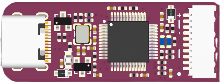
The Mini Debugger by WeActStudio is a compact and versatile tool designed for testing and debugging electronic circuits. It allows developers to monitor signals, diagnose issues in real-time, and ensure the proper functioning of their designs. With its small form factor and robust features, the Mini Debugger is an essential tool for hobbyists, students, and professionals working on embedded systems, microcontrollers, and other electronic projects.

Explore Projects Built with Mini Debugger

Use Cirkit Designer to design, explore, and prototype these projects online. Some projects support real-time simulation. Click "Open Project" to start designing instantly!
I2C-Controlled OLED Display with External EEPROM and Interactive Pushbuttons
Image of godmode: A project utilizing Mini Debugger in a practical application
This is a microcontroller-based interactive device featuring a Wemos D1 Mini, an OLED display, external EEPROM, and an I/O expander. It includes user input buttons and status LEDs, with potential MIDI interface capabilities.
Cirkit Designer LogoOpen Project in Cirkit Designer
ATmega328P-Based Sensor Hub with OLED Display and LIDAR
Image of TILTPCB: A project utilizing Mini Debugger in a practical application
This circuit features an Mtiny Uno ATmega328P microcontroller as its central processing unit, interfacing with a variety of sensors and peripherals. It includes a 0.96" OLED display and an MPU6050 accelerometer/gyroscope for user interface and motion sensing, respectively. The circuit also integrates a TF LUNA LIDAR for distance measurement, a DHT11 sensor for temperature and humidity readings, and uses a 9V battery with a 7805 voltage regulator for power management. Communication with a computer for programming and data exchange is facilitated by an Adafruit FTDI Friend module.
Cirkit Designer LogoOpen Project in Cirkit Designer
Arduino Pro Mini-Based Battery-Powered Temperature and Laser Display System
Image of thermal temperture gun: A project utilizing Mini Debugger in a practical application
This circuit features an Arduino Pro Mini microcontroller interfaced with a USB Serial TTL for programming and power, a momentary switch for user input, and a 9V battery for power supply. It includes a KY-008 laser emitter, a 0.96" OLED display, and an MLX90614 temperature sensor, all connected to the Arduino for a potential temperature measurement and display application.
Cirkit Designer LogoOpen Project in Cirkit Designer
I2C LCD and LED Control via BlynkGate with MakerEDU Shield
Image of kxnTest: A project utilizing Mini Debugger in a practical application
This circuit is designed to interface with Blynk, a platform for controlling Arduino over the internet, and display data on an LCD screen. It includes a MakerEDU Shield connected to two MKE-M01 LED Modules and two MKE-M07 LCD1602 I2C displays for user interaction. The BlynkGate modules are likely used for communication with the Blynk service, and the MTiny Programmer is for programming the microcontrollers. The embedded code suggests that the circuit can receive input via Blynk and display values on the LCDs while also controlling the LEDs.
Cirkit Designer LogoOpen Project in Cirkit Designer

Explore Projects Built with Mini Debugger

Use Cirkit Designer to design, explore, and prototype these projects online. Some projects support real-time simulation. Click "Open Project" to start designing instantly!
Image of godmode: A project utilizing Mini Debugger in a practical application
I2C-Controlled OLED Display with External EEPROM and Interactive Pushbuttons
This is a microcontroller-based interactive device featuring a Wemos D1 Mini, an OLED display, external EEPROM, and an I/O expander. It includes user input buttons and status LEDs, with potential MIDI interface capabilities.
Cirkit Designer LogoOpen Project in Cirkit Designer
Image of TILTPCB: A project utilizing Mini Debugger in a practical application
ATmega328P-Based Sensor Hub with OLED Display and LIDAR
This circuit features an Mtiny Uno ATmega328P microcontroller as its central processing unit, interfacing with a variety of sensors and peripherals. It includes a 0.96" OLED display and an MPU6050 accelerometer/gyroscope for user interface and motion sensing, respectively. The circuit also integrates a TF LUNA LIDAR for distance measurement, a DHT11 sensor for temperature and humidity readings, and uses a 9V battery with a 7805 voltage regulator for power management. Communication with a computer for programming and data exchange is facilitated by an Adafruit FTDI Friend module.
Cirkit Designer LogoOpen Project in Cirkit Designer
Image of thermal temperture gun: A project utilizing Mini Debugger in a practical application
Arduino Pro Mini-Based Battery-Powered Temperature and Laser Display System
This circuit features an Arduino Pro Mini microcontroller interfaced with a USB Serial TTL for programming and power, a momentary switch for user input, and a 9V battery for power supply. It includes a KY-008 laser emitter, a 0.96" OLED display, and an MLX90614 temperature sensor, all connected to the Arduino for a potential temperature measurement and display application.
Cirkit Designer LogoOpen Project in Cirkit Designer
Image of kxnTest: A project utilizing Mini Debugger in a practical application
I2C LCD and LED Control via BlynkGate with MakerEDU Shield
This circuit is designed to interface with Blynk, a platform for controlling Arduino over the internet, and display data on an LCD screen. It includes a MakerEDU Shield connected to two MKE-M01 LED Modules and two MKE-M07 LCD1602 I2C displays for user interaction. The BlynkGate modules are likely used for communication with the Blynk service, and the MTiny Programmer is for programming the microcontrollers. The embedded code suggests that the circuit can receive input via Blynk and display values on the LCDs while also controlling the LEDs.
Cirkit Designer LogoOpen Project in Cirkit Designer

Common Applications and Use Cases

  • Debugging microcontroller-based circuits (e.g., STM32, Arduino, ESP32)
  • Monitoring and analyzing digital and analog signals
  • Testing communication protocols like I2C, SPI, and UART
  • Diagnosing hardware faults in embedded systems
  • Educational purposes for learning circuit debugging techniques

Technical Specifications

Key Technical Details

  • Manufacturer Part ID: Mini Debugger
  • Manufacturer: WeActStudio
  • Power Supply Voltage: 3.3V or 5V (selectable)
  • Supported Protocols: SWD (Serial Wire Debug), JTAG
  • Interface: USB 2.0 (Type-C connector)
  • Supported Microcontrollers: ARM Cortex-M series, STM32, and others
  • Dimensions: 25mm x 15mm x 5mm
  • Operating Temperature: -20°C to 70°C
  • LED Indicators: Power, Data Activity, and Error

Pin Configuration and Descriptions

The Mini Debugger features a standard 10-pin SWD header for connecting to target devices. Below is the pinout:

Pin Number Pin Name Description
1 VCC Target power supply (3.3V or 5V)
2 GND Ground
3 SWDIO Serial Wire Debug I/O
4 SWCLK Serial Wire Debug Clock
5 NRST Target Reset
6 SWO Serial Wire Output (optional)
7 NC Not Connected
8 NC Not Connected
9 NC Not Connected
10 NC Not Connected

Usage Instructions

How to Use the Mini Debugger in a Circuit

  1. Connect the Mini Debugger to the Target Device:

    • Use the 10-pin SWD cable to connect the debugger to the target microcontroller.
    • Ensure the VCC pin matches the target device's operating voltage (3.3V or 5V).
  2. Connect the Mini Debugger to a Computer:

    • Plug the Mini Debugger into your computer using a USB Type-C cable.
    • Install the necessary drivers and debugging software (e.g., OpenOCD, STM32CubeIDE).
  3. Configure the Debugging Software:

    • Select the appropriate interface (SWD or JTAG) in the software.
    • Specify the target microcontroller model and clock speed.
  4. Start Debugging:

    • Use the software to upload firmware, set breakpoints, and monitor signals.
    • Observe the LED indicators for power, data activity, and error status.

Important Considerations and Best Practices

  • Voltage Compatibility: Ensure the target device's voltage matches the VCC pin of the Mini Debugger.
  • Cable Length: Use a short SWD cable to minimize signal degradation.
  • Software Configuration: Double-check the debugging software settings to avoid communication errors.
  • Static Protection: Handle the Mini Debugger and target device in an ESD-safe environment.

Example: Using the Mini Debugger with an Arduino UNO

Although the Arduino UNO does not natively support SWD, you can use the Mini Debugger to monitor UART communication. Below is an example of how to set up UART debugging:

  1. Connect the Mini Debugger's SWO pin to the Arduino's TX pin.
  2. Connect the Mini Debugger's GND pin to the Arduino's GND pin.
  3. Use a terminal program (e.g., PuTTY) to monitor the serial output.

Here is an example Arduino code snippet for UART debugging:

// Example: Sending debug messages via UART
void setup() {
  Serial.begin(9600); // Initialize UART communication at 9600 baud
  Serial.println("Debugging started!"); // Send initial debug message
}

void loop() {
  Serial.println("Monitoring system status..."); // Send periodic debug messages
  delay(1000); // Wait for 1 second
}

Troubleshooting and FAQs

Common Issues and Solutions

Issue Possible Cause Solution
Debugger not detected by computer Missing or incorrect drivers Install the correct drivers from WeActStudio's website.
No communication with target device Incorrect SWD/JTAG connection Verify the pin connections and ensure proper orientation.
Target device not powering on Voltage mismatch or loose connection Check the VCC and GND connections. Ensure voltage compatibility.
Data activity LED not blinking Debugging software misconfiguration Double-check the software settings and target microcontroller model.

FAQs

  1. Can the Mini Debugger be used with non-ARM microcontrollers?

    • The Mini Debugger is primarily designed for ARM Cortex-M microcontrollers. However, it may work with other devices that support SWD or JTAG.
  2. What software is recommended for use with the Mini Debugger?

    • Popular options include OpenOCD, STM32CubeIDE, and Keil uVision.
  3. How do I update the firmware on the Mini Debugger?

    • Firmware updates can be performed using the WeActStudio utility tool. Refer to the manufacturer's website for detailed instructions.
  4. What is the maximum cable length supported by the Mini Debugger?

    • It is recommended to use a cable no longer than 20cm to ensure reliable communication.

By following this documentation, users can effectively utilize the Mini Debugger for their electronic debugging needs.