Cirkit Designer
Your all-in-one circuit design IDE
Home /
Component Documentation
How to Use Digital Airspeed Sensor : Examples, Pinouts, and Specs
Introduction
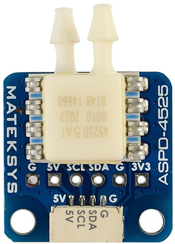
The MATEK ASPD-4525 is a digital airspeed sensor designed to measure the speed of air flowing past it. This sensor provides a digital output, making it suitable for a variety of applications, including aviation, meteorology, and unmanned aerial vehicles (UAVs). The ASPD-4525 is known for its high accuracy and reliability, making it a popular choice among hobbyists and professionals alike.
Explore Projects Built with Digital Airspeed Sensor
Raspberry Pi and H743-SLIM V3 Controlled Servo System with GPS and Telemetry
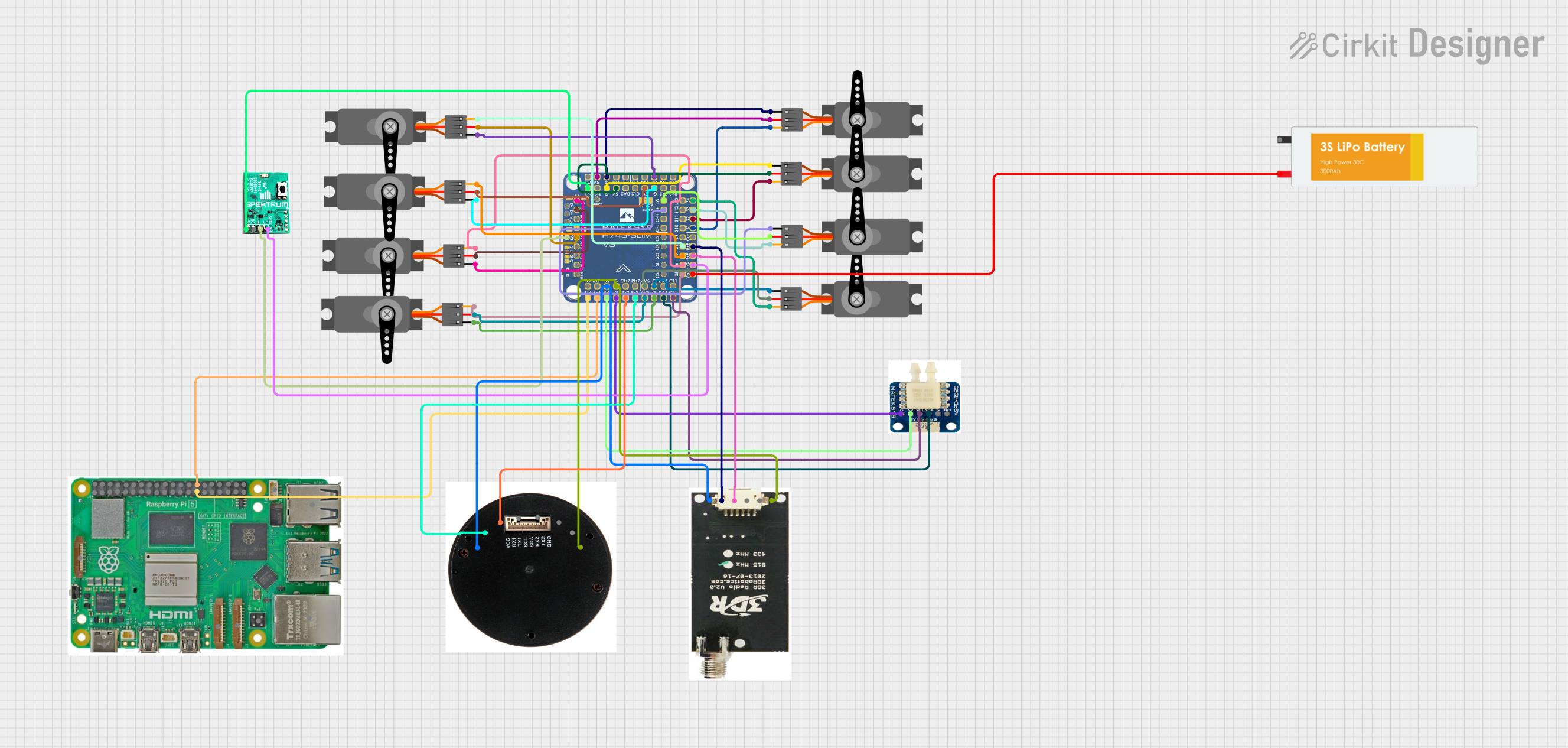
This circuit is designed for a UAV control system, featuring an H743-SLIM V3 flight controller connected to multiple servos for control surfaces, a GPS module for navigation, a telemetry radio for communication, and a digital airspeed sensor for flight data. The system is powered by a LiPo battery and includes a Raspberry Pi for additional processing and control tasks.
Arduino Nano-Based Health Monitoring System with Wi-Fi and GPS
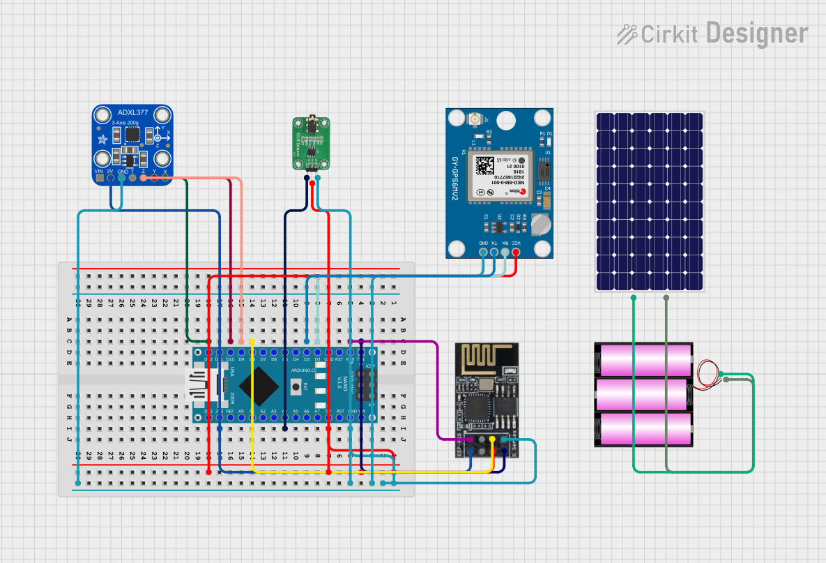
This circuit is a sensor-based data acquisition system using an Arduino Nano, which collects data from a GSR sensor, an ADXL377 accelerometer, and a Neo 6M GPS module. The collected data is then transmitted via a WiFi module (ESP8266-01) for remote monitoring. The system is powered by a 12V battery, which is charged by a solar panel.
Arduino Mega 2560-Based Sensor Data Logger with ESP32-CAM and LCD Interface

This is a multifunctional sensor system with visual feedback and control interfaces. It utilizes an Arduino Mega 2560 to process data from an accelerometer, ultrasonic sensor, and camera module, and displays information on an LCD screen. User inputs can be provided through toggle and DIP switches, while LEDs indicate system status.
Arduino Nano-Based Anemometer with LCD Display
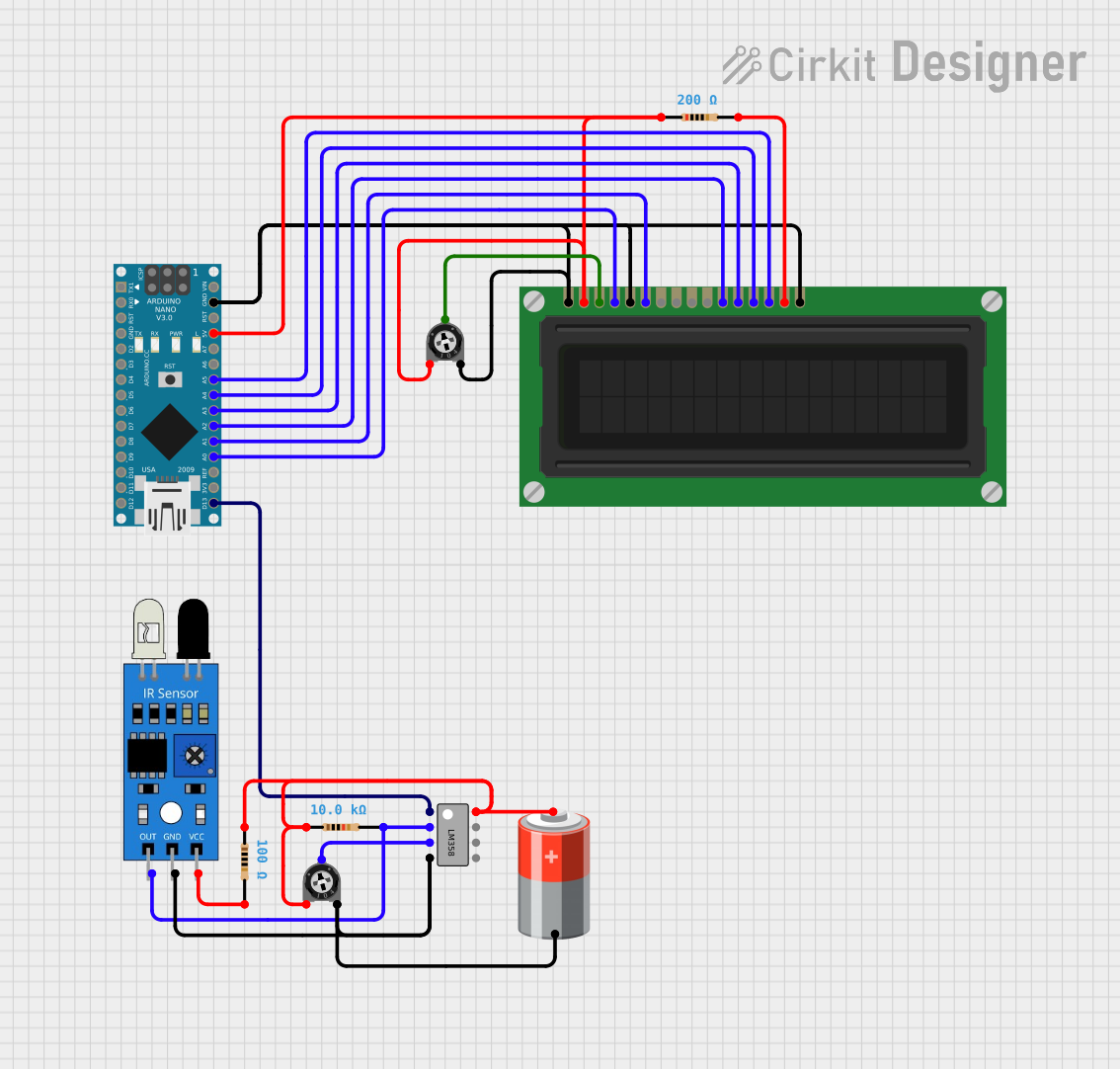
This circuit features an Arduino Nano interfaced with an LCD display, an IR sensor, a dual op-amp LM358, and two trimmer potentiometers. The Arduino is programmed as an anemometer to measure wind speed and direction, displaying the results on the LCD. The IR sensor's output is conditioned by the LM358, and the potentiometers are likely used for setting thresholds or calibration.
Explore Projects Built with Digital Airspeed Sensor
Raspberry Pi and H743-SLIM V3 Controlled Servo System with GPS and Telemetry
This circuit is designed for a UAV control system, featuring an H743-SLIM V3 flight controller connected to multiple servos for control surfaces, a GPS module for navigation, a telemetry radio for communication, and a digital airspeed sensor for flight data. The system is powered by a LiPo battery and includes a Raspberry Pi for additional processing and control tasks.
Arduino Nano-Based Health Monitoring System with Wi-Fi and GPS
This circuit is a sensor-based data acquisition system using an Arduino Nano, which collects data from a GSR sensor, an ADXL377 accelerometer, and a Neo 6M GPS module. The collected data is then transmitted via a WiFi module (ESP8266-01) for remote monitoring. The system is powered by a 12V battery, which is charged by a solar panel.
Arduino Mega 2560-Based Sensor Data Logger with ESP32-CAM and LCD Interface
This is a multifunctional sensor system with visual feedback and control interfaces. It utilizes an Arduino Mega 2560 to process data from an accelerometer, ultrasonic sensor, and camera module, and displays information on an LCD screen. User inputs can be provided through toggle and DIP switches, while LEDs indicate system status.
Arduino Nano-Based Anemometer with LCD Display
This circuit features an Arduino Nano interfaced with an LCD display, an IR sensor, a dual op-amp LM358, and two trimmer potentiometers. The Arduino is programmed as an anemometer to measure wind speed and direction, displaying the results on the LCD. The IR sensor's output is conditioned by the LM358, and the potentiometers are likely used for setting thresholds or calibration.
Technical Specifications
Key Technical Details
| Parameter | Value |
|---|---|
| Supply Voltage | 3.3V to 5.5V |
| Operating Current | 5mA |
| Measurement Range | 0 to 100 m/s |
| Accuracy | ±1% |
| Interface | I2C |
| Operating Temperature | -40°C to 85°C |
| Dimensions | 25mm x 15mm x 5mm |
Pin Configuration and Descriptions
| Pin Number | Pin Name | Description |
|---|---|---|
| 1 | VCC | Power supply (3.3V to 5.5V) |
| 2 | GND | Ground |
| 3 | SDA | I2C data line |
| 4 | SCL | I2C clock line |
Usage Instructions
How to Use the Component in a Circuit
- Power Supply: Connect the VCC pin to a 3.3V or 5V power supply and the GND pin to the ground of your circuit.
- I2C Communication: Connect the SDA pin to the SDA line of your microcontroller and the SCL pin to the SCL line of your microcontroller.
- Pull-up Resistors: Ensure that the I2C lines (SDA and SCL) have appropriate pull-up resistors (typically 4.7kΩ).
Important Considerations and Best Practices
- Power Supply: Ensure that the power supply voltage is within the specified range (3.3V to 5.5V) to avoid damaging the sensor.
- I2C Address: The default I2C address for the ASPD-4525 is 0x28. Ensure that this address does not conflict with other devices on the I2C bus.
- Calibration: For accurate measurements, calibrate the sensor according to the manufacturer's guidelines.
- Environmental Conditions: Avoid exposing the sensor to extreme temperatures or humidity levels beyond its operating range.
Example Code for Arduino UNO
#include <Wire.h>

#define AIRSPEED_SENSOR_ADDR 0x28 // Default I2C address for ASPD-4525

void setup() {
  Serial.begin(9600); // Initialize serial communication at 9600 baud
  Wire.begin();       // Initialize I2C communication
}

void loop() {
  Wire.beginTransmission(AIRSPEED_SENSOR_ADDR);
  Wire.write(0x00); // Request data from the sensor
  Wire.endTransmission();

  Wire.requestFrom(AIRSPEED_SENSOR_ADDR, 2); // Request 2 bytes of data

  if (Wire.available() == 2) {
    int16_t rawData = Wire.read() << 8 | Wire.read();
    float airspeed = rawData * 0.1; // Convert raw data to airspeed in m/s

    Serial.print("Airspeed: ");
    Serial.print(airspeed);
    Serial.println(" m/s");
  }

  delay(1000); // Wait for 1 second before next reading
}
Troubleshooting and FAQs
Common Issues Users Might Face
- No Data Output: Ensure that the sensor is properly connected to the power supply and I2C lines. Check for loose connections or broken wires.
- Incorrect Readings: Verify that the sensor is calibrated correctly. Ensure that the environmental conditions are within the specified operating range.
- I2C Communication Errors: Check the I2C address and ensure that there are no conflicts with other devices on the bus. Verify that the pull-up resistors are correctly installed.
Solutions and Tips for Troubleshooting
- Check Connections: Double-check all connections to ensure that they are secure and correctly wired.
- Use a Logic Analyzer: If you are experiencing I2C communication issues, use a logic analyzer to monitor the I2C bus and identify any problems.
- Consult the Datasheet: Refer to the manufacturer's datasheet for detailed information on the sensor's operation and troubleshooting tips.
By following this documentation, users can effectively integrate the MATEK ASPD-4525 digital airspeed sensor into their projects, ensuring accurate and reliable airspeed measurements.