How to Use PCM1808 Module: Examples, Pinouts, and Specs
Introduction
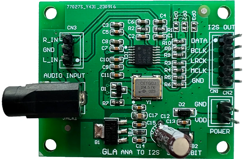
The PCM1808 Module is a high-performance audio analog-to-digital converter (ADC) designed to convert analog audio signals into high-resolution digital data. Manufactured by Texas Instruments, the PCM1808 offers 24-bit resolution and supports sampling rates up to 192 kHz, making it ideal for high-fidelity audio applications. Its compact design and low power consumption make it suitable for a wide range of audio processing systems, including audio recording devices, digital mixers, and home theater systems.
Explore Projects Built with PCM1808 Module


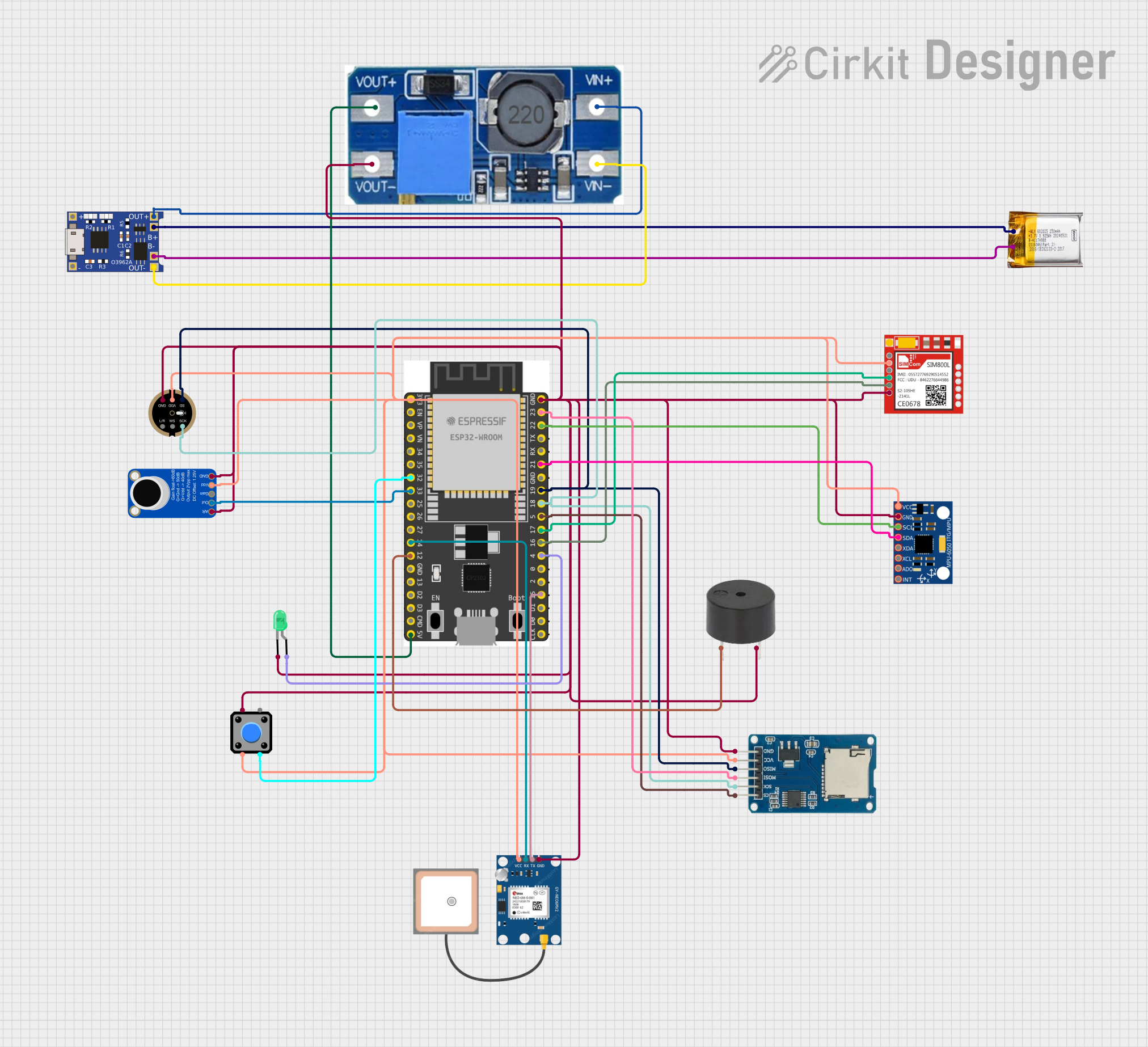
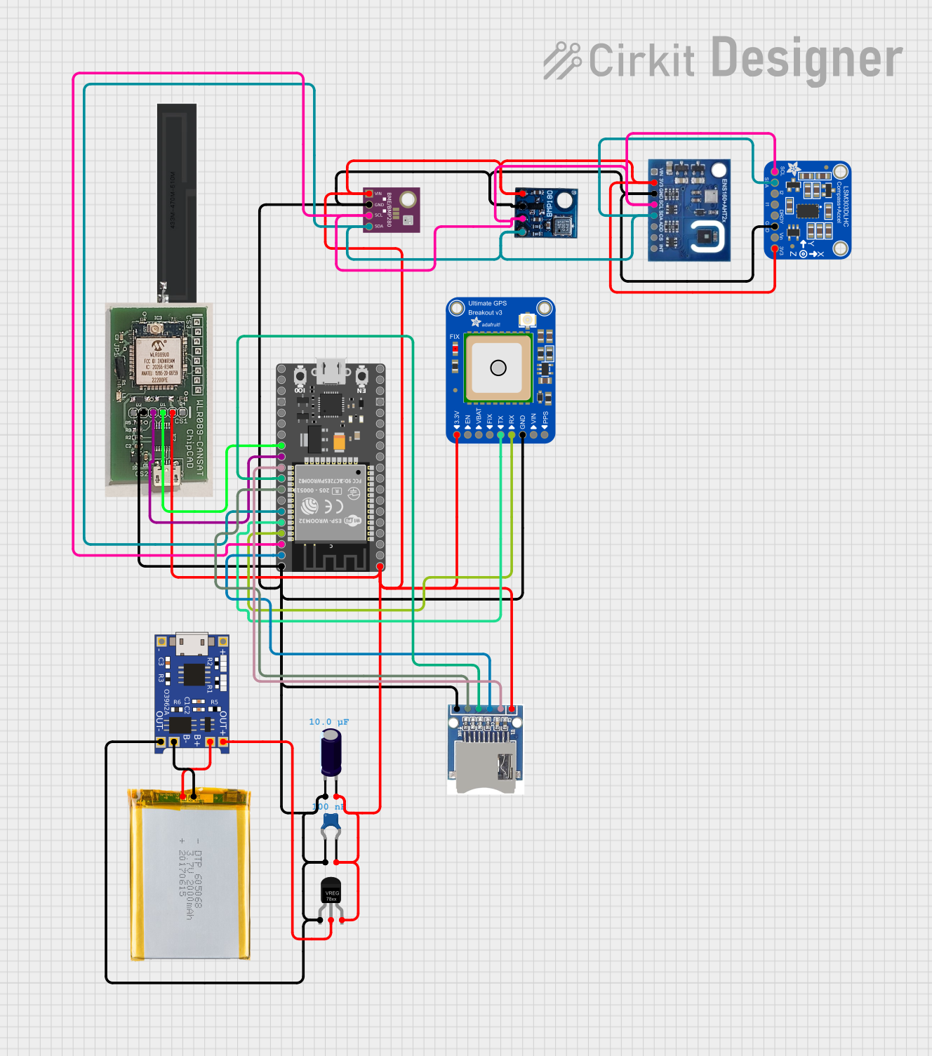
Explore Projects Built with PCM1808 Module
Common Applications and Use Cases
- High-fidelity audio recording and playback systems
- Digital audio mixers and signal processors
- Home theater and multimedia systems
- Audio measurement and analysis equipment
- Embedded systems requiring audio digitization
Technical Specifications
The PCM1808 Module is built to deliver exceptional audio performance with minimal distortion and noise. Below are its key technical specifications:
| Parameter | Value |
|---|---|
| Resolution | 24-bit |
| Sampling Rate | Up to 192 kHz |
| Signal-to-Noise Ratio (SNR) | 99 dB (typical) |
| Total Harmonic Distortion + Noise (THD+N) | 0.002% (typical) |
| Input Voltage Range | 0.6 Vpp to 2.1 Vpp |
| Power Supply Voltage | 3.3 V |
| Power Consumption | 20 mW (typical) |
| Operating Temperature Range | -25°C to 85°C |
| Package Type | TSSOP-14 |
Pin Configuration and Descriptions
The PCM1808 Module features a 14-pin configuration. Below is the pinout and description:
| Pin Number | Pin Name | Description |
|---|---|---|
| 1 | VINL | Left-channel analog audio input |
| 2 | VINR | Right-channel analog audio input |
| 3 | VREF | Reference voltage output |
| 4 | AGND | Analog ground |
| 5 | VCC | Power supply (3.3 V) |
| 6 | DGND | Digital ground |
| 7 | BCK | Bit clock input for I2S |
| 8 | LRCK | Left-right clock input for I2S |
| 9 | DOUT | Digital audio data output |
| 10 | SCKI | System clock input |
| 11 | MODE | Mode selection pin (high: master, low: slave) |
| 12 | FMT | Audio data format selection |
| 13 | PDWN | Power-down control (active low) |
| 14 | TEST | Test pin (must be connected to ground) |
Usage Instructions
How to Use the PCM1808 Module in a Circuit
- Power Supply: Connect the VCC pin to a stable 3.3 V power source and connect AGND and DGND to the ground.
- Audio Input: Feed the left and right analog audio signals to the VINL and VINR pins, respectively. Ensure the input voltage is within the specified range (0.6 Vpp to 2.1 Vpp).
- Clock Signals: Provide the necessary clock signals (SCKI, BCK, and LRCK) for the I2S interface. The SCKI clock should be 256, 384, or 512 times the sampling frequency.
- Audio Data Output: Connect the DOUT pin to the digital audio receiver or microcontroller to capture the I2S audio data.
- Mode Selection: Use the MODE pin to configure the module as a master or slave device. In master mode, the PCM1808 generates the BCK and LRCK signals.
- Audio Format: Configure the FMT pin to select the desired audio data format (e.g., I2S, left-justified, or right-justified).
- Power-Down Control: Use the PDWN pin to enable or disable the module. Pulling this pin low puts the module into a low-power state.
Important Considerations and Best Practices
- Use decoupling capacitors near the power supply pins to minimize noise and ensure stable operation.
- Ensure proper grounding to avoid introducing noise into the audio signal.
- Use shielded cables for analog audio inputs to reduce electromagnetic interference.
- If using the PCM1808 with a microcontroller, ensure the I2S clock signals are synchronized with the module's requirements.
Example: Connecting PCM1808 to Arduino UNO
The PCM1808 can be interfaced with an Arduino UNO using the I2S protocol. Below is an example Arduino sketch to read audio data from the PCM1808:
#include <I2S.h> // Include the I2S library for Arduino

void setup() {
  // Initialize serial communication for debugging
  Serial.begin(9600);

  // Initialize I2S as a receiver
  if (!I2S.begin(I2S_PHILIPS_MODE, 44100, 32)) {
    Serial.println("Failed to initialize I2S!");
    while (1); // Halt execution if initialization fails
  }

  Serial.println("PCM1808 Module Initialized!");
}

void loop() {
  // Check if audio data is available
  if (I2S.available()) {
    int audioData = I2S.read(); // Read audio data from PCM1808
    Serial.println(audioData); // Print the audio data to the serial monitor
  }
}
Note: The Arduino UNO does not natively support I2S. Use an Arduino board with I2S capability (e.g., Arduino Nano 33 IoT or ESP32) for this example.
Troubleshooting and FAQs
Common Issues and Solutions
No Audio Output:
- Verify that the clock signals (SCKI, BCK, and LRCK) are correctly configured and synchronized.
- Ensure the analog audio input signals are within the specified voltage range.
Distorted Audio:
- Check for noise or interference in the analog input signals.
- Ensure proper grounding and use shielded cables for audio inputs.
Module Not Powering On:
- Verify the power supply voltage is 3.3 V.
- Check the connections to the VCC and ground pins.
I2S Communication Issues:
- Ensure the microcontroller's I2S settings match the PCM1808's configuration.
- Verify the MODE and FMT pin settings for the desired operation mode and audio format.
FAQs
Q: Can the PCM1808 operate at 5 V?
A: No, the PCM1808 is designed to operate at a power supply voltage of 3.3 V. Using a higher voltage may damage the module.
Q: What is the maximum sampling rate supported by the PCM1808?
A: The PCM1808 supports sampling rates up to 192 kHz.
Q: Can I use the PCM1808 with a Raspberry Pi?
A: Yes, the PCM1808 can be interfaced with a Raspberry Pi using the I2S interface. Ensure the clock signals and audio format are configured correctly.
Q: How do I select the audio data format?
A: Use the FMT pin to select the desired audio data format. Refer to the PCM1808 datasheet for the specific pin configurations.
This concludes the documentation for the PCM1808 Module. For further details, refer to the official datasheet or contact the manufacturer.