
How to Use Converter 24V to 5V: Examples, Pinouts, and Specs
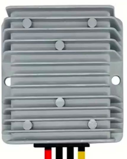
 Design with Converter 24V to 5V in Cirkit Designer
Introduction
The 24V to 5V converter is an electronic device designed to step down a 24V input voltage to a stable 5V output. This component is widely used in applications where low-voltage electronics, such as microcontrollers, sensors, and communication modules, need to be powered from higher voltage sources like industrial power supplies, automotive systems, or solar panels. Its compact design and high efficiency make it an essential component in embedded systems, robotics, and IoT devices.
Explore Projects Built with Converter 24V to 5V
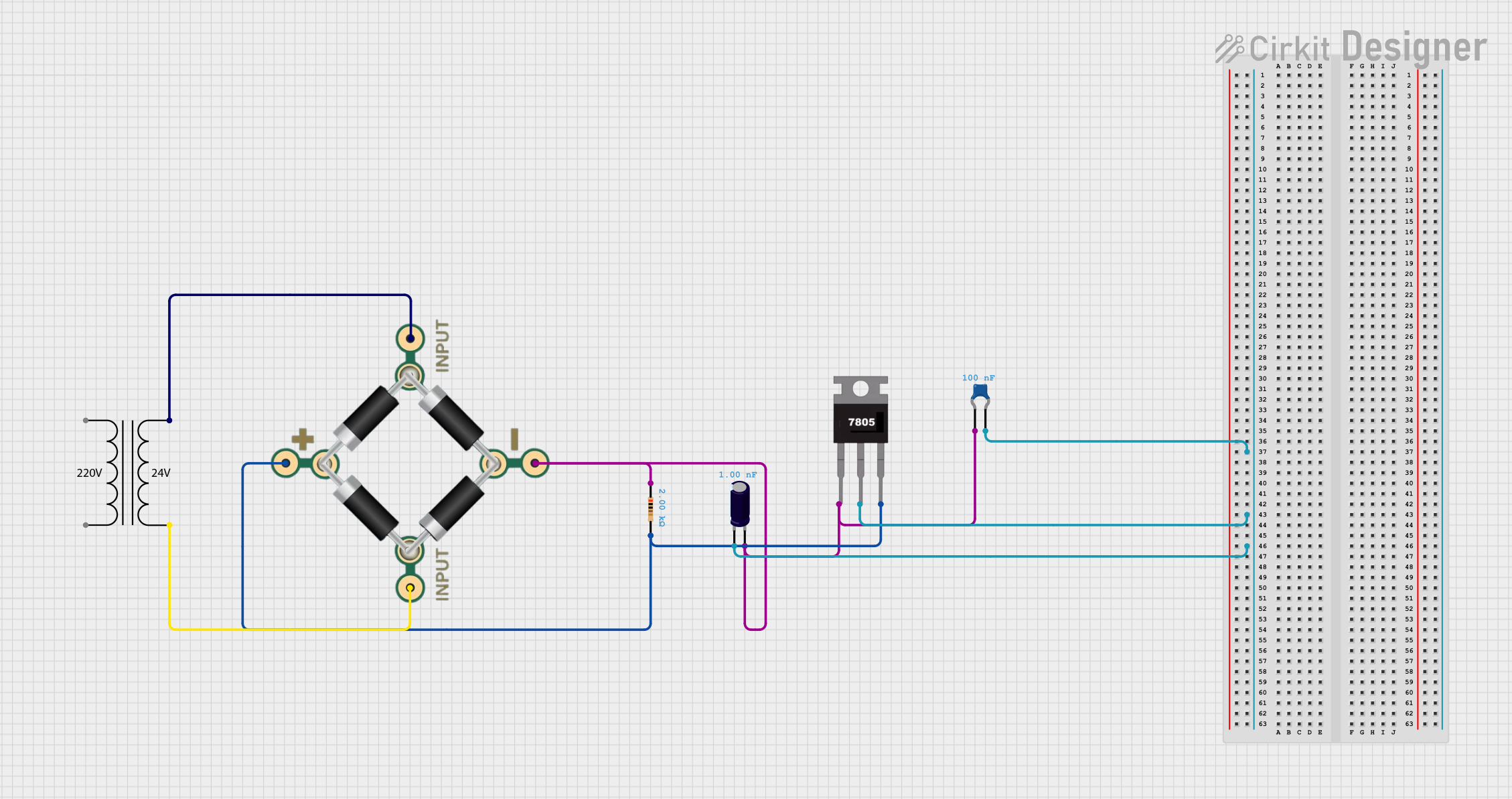 Open Project in Cirkit Designer
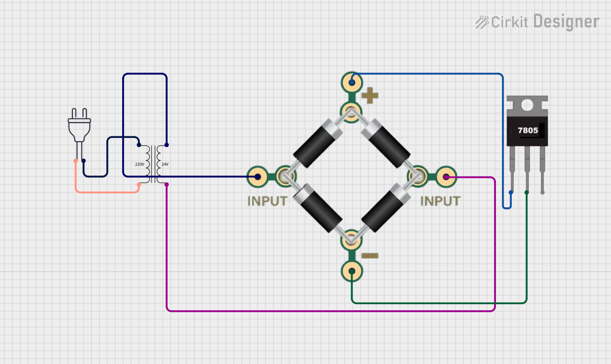 Open Project in Cirkit Designer
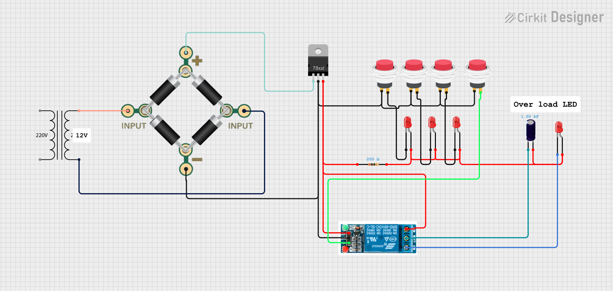 Open Project in Cirkit Designer
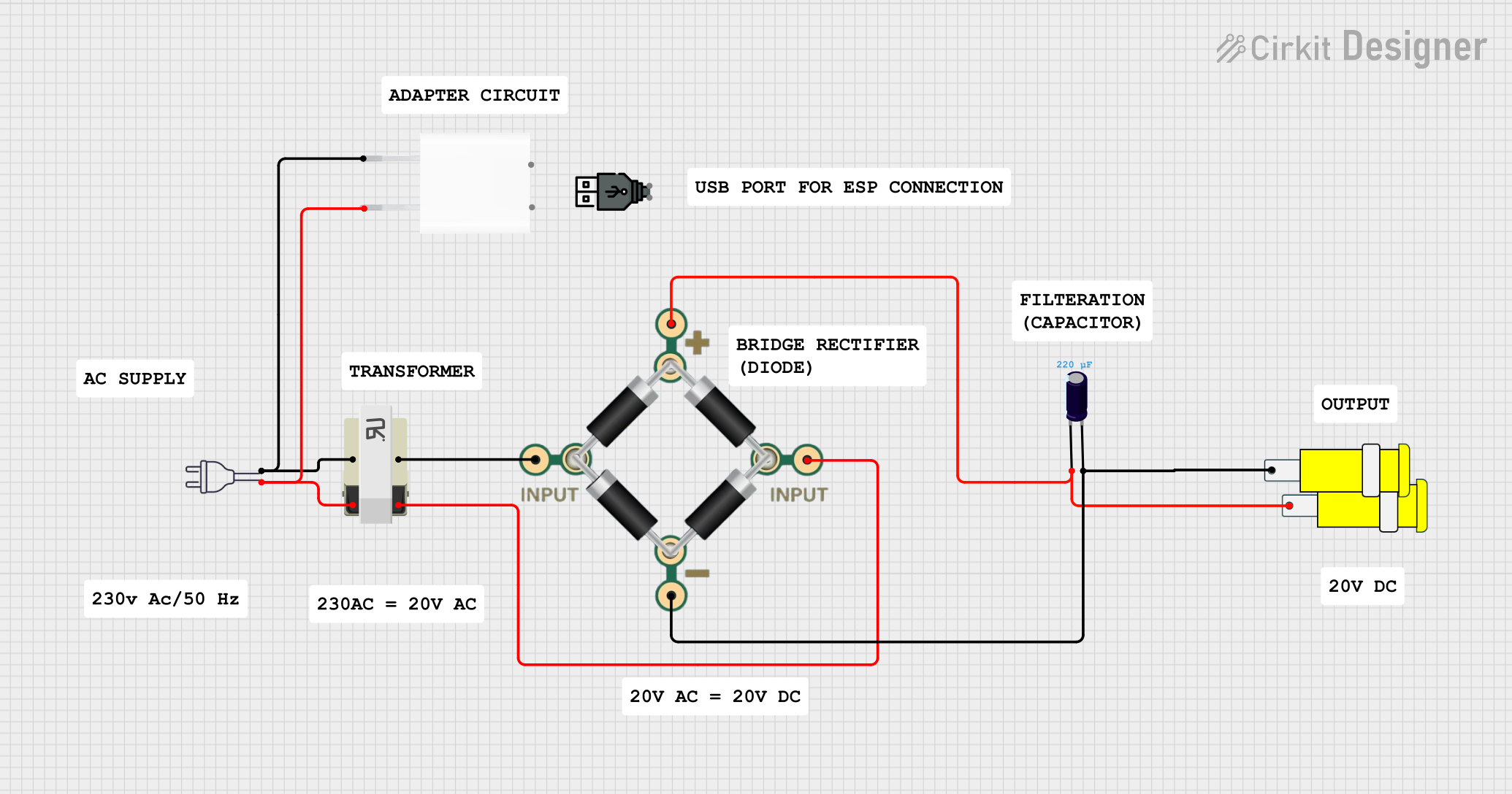 Open Project in Cirkit Designer
Explore Projects Built with Converter 24V to 5V
Open Project in Cirkit DesignerOpen Project in Cirkit DesignerOpen Project in Cirkit DesignerOpen Project in Cirkit DesignerCommon Applications
- Powering microcontrollers (e.g., Arduino, Raspberry Pi) from 24V sources
- Supplying 5V to sensors, relays, and communication modules
- Automotive electronics and industrial control systems
- Battery-powered systems with 24V battery packs
- Solar-powered devices requiring a 5V output
Technical Specifications
Below are the key technical details of the 24V to 5V converter:
| Parameter | Value |
|---|---|
| Input Voltage Range | 18V to 36V |
| Output Voltage | 5V ± 0.1V |
| Maximum Output Current | 3A |
| Efficiency | Up to 95% |
| Ripple and Noise | < 50mV |
| Operating Temperature | -40°C to +85°C |
| Protection Features | Overcurrent, Overvoltage, Thermal |
| Dimensions | 25mm x 20mm x 10mm |
Pin Configuration
The converter typically has four pins or terminals for input and output connections. The table below describes each pin:
| Pin | Name | Description |
|---|---|---|
| 1 | VIN+ | Positive input voltage (18V to 36V) |
| 2 | VIN- | Negative input voltage (Ground) |
| 3 | VOUT+ | Positive output voltage (5V) |
| 4 | VOUT- | Negative output voltage (Ground, same as VIN-) |
Usage Instructions
How to Use the Converter in a Circuit
- Connect the Input Voltage:
- Connect the VIN+ pin to the positive terminal of the 24V power source.
- Connect the VIN- pin to the ground terminal of the power source.
- Connect the Output Voltage:
- Connect the VOUT+ pin to the positive terminal of the load (e.g., microcontroller, sensor).
- Connect the VOUT- pin to the ground terminal of the load.
- Verify Connections:
- Double-check all connections to ensure proper polarity and avoid short circuits.
- Power On:
- Turn on the 24V power source. The converter will step down the voltage to 5V and supply it to the connected load.
Important Considerations
- Input Voltage Range: Ensure the input voltage is within the specified range (18V to 36V). Exceeding this range may damage the converter.
- Load Current: Do not exceed the maximum output current (3A). Overloading the converter can trigger protection features or cause overheating.
- Heat Dissipation: If the converter operates near its maximum current rating, ensure adequate ventilation or use a heatsink to prevent overheating.
- Polarity: Always connect the input and output terminals with the correct polarity to avoid damage.
Example: Using the Converter with an Arduino UNO
The 24V to 5V converter can be used to power an Arduino UNO from a 24V power source. Below is an example circuit and Arduino code to blink an LED:
Circuit Connections
- Connect the VIN+ and VIN- pins of the converter to the 24V power source.
- Connect the VOUT+ pin to the 5V pin on the Arduino UNO.
- Connect the VOUT- pin to the GND pin on the Arduino UNO.
- Connect an LED with a 220-ohm resistor to pin 13 of the Arduino UNO.
Arduino Code
// This code blinks an LED connected to pin 13 of the Arduino UNO.
// Ensure the 24V to 5V converter is properly connected to power the Arduino.

void setup() {
  pinMode(13, OUTPUT); // Set pin 13 as an output pin
}

void loop() {
  digitalWrite(13, HIGH); // Turn the LED on
  delay(1000);            // Wait for 1 second
  digitalWrite(13, LOW);  // Turn the LED off
  delay(1000);            // Wait for 1 second
}
Troubleshooting and FAQs
Common Issues and Solutions
No Output Voltage:
- Cause: Incorrect input connections or insufficient input voltage.
- Solution: Verify the input voltage is within the specified range (18V to 36V) and check the polarity of the connections.
Overheating:
- Cause: Excessive load current or poor ventilation.
- Solution: Reduce the load current or improve ventilation around the converter. Consider using a heatsink if necessary.
Output Voltage Fluctuations:
- Cause: High ripple on the input voltage or unstable load.
- Solution: Add a capacitor (e.g., 100µF) across the input and output terminals to stabilize the voltage.
Converter Not Powering the Load:
- Cause: Load current exceeds the maximum rating.
- Solution: Ensure the load current is below 3A. Use a higher-rated converter if needed.
FAQs
Q: Can I use this converter to power a Raspberry Pi?
A: Yes, the converter can power a Raspberry Pi as long as the total current draw (including peripherals) does not exceed 3A.
Q: Is the converter waterproof?
A: No, the converter is not waterproof. Use it in a dry environment or enclose it in a waterproof case if necessary.
Q: Can I connect multiple converters in parallel for higher current?
A: It is not recommended to connect converters in parallel unless they are specifically designed for parallel operation.
Q: What happens if the input voltage drops below 18V?
A: The converter may stop functioning or output an unstable voltage. Ensure the input voltage remains within the specified range.