How to Use 11KW KONTAKTOR + OVERLOAD: Examples, Pinouts, and Specs
Introduction
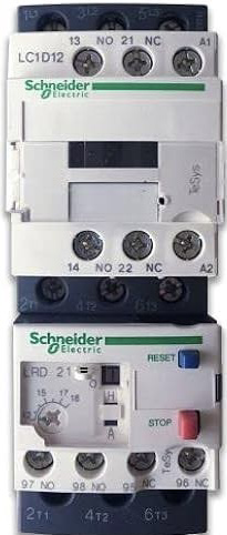
The 11KW KONTAKTOR + OVERLOAD (Manufacturer: Schneider, Part ID: MCE 2-25) is an electromechanical device designed to control and protect electrical circuits, particularly for motor applications. This contactor is rated for 11 kW and includes an integrated overload relay to safeguard motors from overheating or damage caused by excessive current. It is widely used in industrial automation, HVAC systems, and motor control centers.
Explore Projects Built with 11KW KONTAKTOR + OVERLOAD


Explore Projects Built with 11KW KONTAKTOR + OVERLOAD
Common Applications:
- Motor control in industrial machinery
- HVAC systems for compressors and fans
- Conveyor systems
- Pumps and water treatment plants
- General-purpose power switching in automation systems
Technical Specifications
Key Technical Details:
| Parameter | Value |
|---|---|
| Manufacturer | Schneider |
| Part ID | MCE 2-25 |
| Rated Power | 11 kW |
| Rated Voltage | Up to 690V AC |
| Rated Current | 25 A |
| Control Voltage | 24V AC/DC, 110V AC, or 230V AC |
| Number of Poles | 3 (Three-phase) |
| Overload Relay Range | Adjustable (e.g., 6-25 A) |
| Operating Temperature | -20°C to +60°C |
| Mechanical Durability | 10 million operations |
| Electrical Durability | 1 million operations |
| Mounting Type | DIN rail or panel mount |
Pin Configuration and Descriptions:
The contactor and overload relay have terminals for power connections, control signals, and auxiliary contacts. Below is the pin configuration:
Contactor Terminals:
| Terminal Label | Description |
|---|---|
| L1, L2, L3 | Input terminals for three-phase power |
| T1, T2, T3 | Output terminals to the load (motor) |
| A1, A2 | Coil terminals for control voltage |
Overload Relay Terminals:
| Terminal Label | Description |
|---|---|
| 95, 96 | Normally Closed (NC) auxiliary contact for overload trip |
| 97, 98 | Normally Open (NO) auxiliary contact for overload trip |
| T1, T2, T3 | Pass-through connections to the motor load |
Usage Instructions
How to Use the Component in a Circuit:
Power Connections:
- Connect the three-phase power supply to the input terminals (L1, L2, L3).
- Connect the motor or load to the output terminals (T1, T2, T3).
Control Circuit:
- Supply the appropriate control voltage (e.g., 24V AC/DC) to the coil terminals (A1, A2).
- Use a push-button switch or PLC output to control the contactor coil.
Overload Relay Setup:
- Adjust the overload relay to match the motor's full-load current using the dial on the relay.
- Connect the auxiliary contacts (95-96 or 97-98) to the control circuit for overload protection.
Mounting:
- Secure the contactor and overload relay on a DIN rail or panel using screws.
Testing:
- After wiring, test the circuit by energizing the coil and verifying that the contactor switches the load correctly.
- Simulate an overload condition to ensure the relay trips and disconnects the power.
Important Considerations and Best Practices:
- Ensure the contactor's rated current and voltage match the application requirements.
- Use proper wire sizes and tighten all connections securely to prevent overheating.
- Install surge suppressors across the coil terminals to protect against voltage spikes.
- Regularly inspect the contactor and relay for wear or damage, especially in high-duty-cycle applications.
- For safety, always disconnect power before performing maintenance or adjustments.
Example: Connecting to an Arduino UNO
The contactor can be controlled using an Arduino UNO by driving the coil with a relay module or transistor circuit. Below is an example code snippet:
// Example: Controlling the 11KW KONTAKTOR with Arduino UNO
// This code uses pin 7 to control the contactor via a relay module.

const int contactorPin = 7; // Pin connected to the relay module

void setup() {
  pinMode(contactorPin, OUTPUT); // Set pin as output
  digitalWrite(contactorPin, LOW); // Ensure contactor is off initially
}

void loop() {
  // Turn the contactor ON
  digitalWrite(contactorPin, HIGH);
  delay(5000); // Keep it ON for 5 seconds

  // Turn the contactor OFF
  digitalWrite(contactorPin, LOW);
  delay(5000); // Keep it OFF for 5 seconds
}
Note: Use a relay module or transistor circuit to interface the Arduino with the contactor coil, as the Arduino cannot directly drive the coil due to current limitations.
Troubleshooting and FAQs
Common Issues and Solutions:
Contactor Does Not Energize:
- Cause: No control voltage at the coil terminals (A1, A2).
- Solution: Verify the control voltage source and ensure proper wiring.
Overload Relay Trips Frequently:
- Cause: Overload relay setting is too low or motor is drawing excessive current.
- Solution: Adjust the relay setting to match the motor's full-load current. Check for mechanical issues with the motor.
Excessive Noise or Chattering:
- Cause: Voltage fluctuations or loose connections.
- Solution: Stabilize the control voltage and tighten all connections.
Burnt Contacts:
- Cause: Overcurrent or frequent switching.
- Solution: Replace the contactor and ensure the load current is within the rated limits.
Motor Does Not Start:
- Cause: Incorrect wiring or faulty contactor.
- Solution: Double-check the wiring and test the contactor coil with a multimeter.
FAQs:
Q: Can this contactor be used for single-phase motors?
A: Yes, but only two poles (L1 and L2) will be used for single-phase applications.Q: How do I reset the overload relay after a trip?
A: Press the reset button on the relay after resolving the overload condition.Q: Can I use this contactor for DC loads?
A: No, this contactor is designed for AC loads. Use a DC-rated contactor for DC applications.Q: What is the lifespan of this contactor?
A: The mechanical durability is rated for 10 million operations, while the electrical durability is rated for 1 million operations under normal conditions.
By following this documentation, users can effectively integrate and maintain the 11KW KONTAKTOR + OVERLOAD in their electrical systems.