How to Use PCM5102A: Examples, Pinouts, and Specs
Introduction
The PCM5102A is a high-performance digital-to-analog converter (DAC) manufactured by Texas Instruments. It is designed specifically for audio applications, offering 32-bit audio processing, low distortion, and a high signal-to-noise ratio (SNR). These features make it an excellent choice for high-fidelity audio systems, including home audio equipment, professional audio devices, and portable audio players.
Explore Projects Built with PCM5102A


Explore Projects Built with PCM5102A
Common Applications and Use Cases
- High-fidelity home audio systems
- Professional audio equipment
- Portable audio players
- Digital audio streaming devices
- Audio signal processing in embedded systems
Technical Specifications
Key Technical Details
| Parameter | Value |
|---|---|
| Audio Resolution | 32-bit |
| Sampling Rate | Up to 384 kHz |
| Signal-to-Noise Ratio (SNR) | 112 dB (typical) |
| Total Harmonic Distortion + Noise (THD+N) | -93 dB (typical) |
| Power Supply Voltage | 3.3V (analog and digital) |
| Output Voltage | 2.1 Vrms (typical) |
| Interface | I2S (Inter-IC Sound) |
| Operating Temperature Range | -25°C to 85°C |
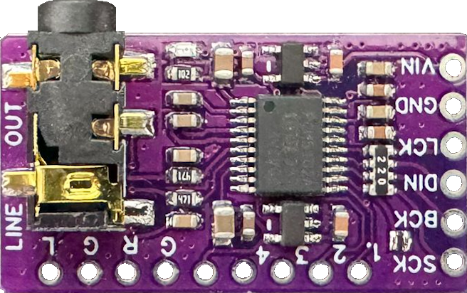
Pin Configuration and Descriptions
The PCM5102A is typically available in a 20-pin TSSOP package. Below is the pin configuration and description:
| Pin Number | Pin Name | Description |
|---|---|---|
| 1 | GND | Ground (common for analog and digital) |
| 2 | VDD | Digital power supply (3.3V) |
| 3 | LRCK | Left/Right clock input for I2S |
| 4 | BCK | Bit clock input for I2S |
| 5 | DIN | Digital audio data input (I2S format) |
| 6 | SCK | System clock input (optional) |
| 7 | FMT | Audio format selection (I2S, left-justified) |
| 8 | XSMT | Soft mute control |
| 9 | FLT | Filter response selection |
| 10 | VCOM | Common voltage reference |
| 11 | VOUTL | Left channel analog output |
| 12 | VOUTR | Right channel analog output |
| 13 | VCC | Analog power supply (3.3V) |
| 14 | GND | Ground |
| 15-20 | NC | No connection |
Usage Instructions
How to Use the PCM5102A in a Circuit
- Power Supply: Connect the VDD and VCC pins to a stable 3.3V power supply. Ensure proper decoupling capacitors (e.g., 0.1 µF and 10 µF) are placed close to the power pins to minimize noise.
- Grounding: Connect all GND pins to a common ground plane to ensure proper operation and minimize noise.
- I2S Interface:
- Connect the LRCK, BCK, and DIN pins to the corresponding I2S signals from the audio source (e.g., a microcontroller or audio processor).
- If a system clock (SCK) is required, provide a stable clock signal to the SCK pin.
- Audio Output:
- Connect the VOUTL and VOUTR pins to the left and right audio output channels, respectively.
- Use appropriate filtering and amplification circuits if needed for your application.
- Control Pins: Configure the FMT, XSMT, and FLT pins as required:
- FMT: Select the desired audio format (e.g., I2S or left-justified).
- XSMT: Use this pin to enable or disable soft mute.
- FLT: Choose the desired filter response for audio output.
Important Considerations and Best Practices
- Clock Configuration: Ensure the I2S clocks (LRCK, BCK, and optionally SCK) are configured correctly to match the audio sampling rate and bit depth.
- PCB Layout: Use a proper PCB layout with a solid ground plane and short signal traces to minimize noise and interference.
- Decoupling: Place decoupling capacitors close to the power supply pins to ensure stable operation.
- Output Loading: Avoid excessive loading on the VOUTL and VOUTR pins to prevent distortion.
Example: Connecting PCM5102A to an Arduino UNO
The PCM5102A can be connected to an Arduino UNO using the I2S interface. However, note that the Arduino UNO does not natively support I2S. You may need an external I2S interface module or use a microcontroller with native I2S support (e.g., ESP32).
Here is an example code snippet for an ESP32:
#include <driver/i2s.h>

// I2S configuration for PCM5102A
void setupI2S() {
  i2s_config_t i2s_config = {
    .mode = (i2s_mode_t)(I2S_MODE_MASTER | I2S_MODE_TX), // Master, Transmit
    .sample_rate = 44100,                               // 44.1 kHz sample rate
    .bits_per_sample = I2S_BITS_PER_SAMPLE_16BIT,       // 16-bit audio
    .channel_format = I2S_CHANNEL_FMT_RIGHT_LEFT,       // Stereo format
    .communication_format = I2S_COMM_FORMAT_I2S,        // I2S standard
    .intr_alloc_flags = 0,                              // Default interrupt
    .dma_buf_count = 8,                                 // Number of DMA buffers
    .dma_buf_len = 64,                                  // Size of each DMA buffer
    .use_apll = false                                   // Disable APLL
  };

  // Pin configuration for I2S
  i2s_pin_config_t pin_config = {
    .bck_io_num = 26,   // Bit clock pin
    .ws_io_num = 25,    // Word select (LRCK) pin
    .data_out_num = 22, // Data output pin
    .data_in_num = -1   // Not used
  };

  // Install and start I2S driver
  i2s_driver_install(I2S_NUM_0, &i2s_config, 0, NULL);
  i2s_set_pin(I2S_NUM_0, &pin_config);
}

void setup() {
  setupI2S(); // Initialize I2S
}

void loop() {
  // Example: Send audio data to PCM5102A
  uint8_t audio_data[64] = {0}; // Replace with actual audio data
  size_t bytes_written;
  i2s_write(I2S_NUM_0, audio_data, sizeof(audio_data), &bytes_written, portMAX_DELAY);
}
Troubleshooting and FAQs
Common Issues and Solutions
No Audio Output:
- Verify that the I2S signals (LRCK, BCK, and DIN) are correctly connected and configured.
- Check the power supply and ensure proper decoupling capacitors are in place.
- Ensure the audio source is providing valid I2S data.
Distorted Audio:
- Check the output loading on the VOUTL and VOUTR pins. Excessive loading can cause distortion.
- Verify the clock configuration (sampling rate and bit depth) matches the audio source.
High Noise or Interference:
- Ensure a proper PCB layout with a solid ground plane.
- Minimize the length of signal traces and use shielded cables if necessary.
FAQs
Q: Can the PCM5102A operate at 5V?
A: No, the PCM5102A is designed to operate at 3.3V for both analog and digital power supplies.
Q: Does the PCM5102A support mono audio?
A: The PCM5102A is designed for stereo audio output. However, you can use only one channel (e.g., VOUTL) if mono output is required.
Q: Is an external clock required for the PCM5102A?
A: The PCM5102A can operate without an external system clock (SCK) in some configurations, but providing a stable SCK is recommended for optimal performance.