
How to Use Pololu 12V 4.5A DC-DC Step-Down Voltage Regulator: Examples, Pinouts, and Specs
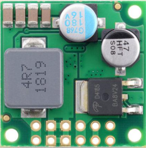
 Design with Pololu 12V 4.5A DC-DC Step-Down Voltage Regulator in Cirkit Designer
Introduction
The Pololu 12V 4.5A DC-DC Step-Down Voltage Regulator is a compact and efficient voltage regulator designed to convert a higher input voltage into a stable 12V output. With a maximum output current of 4.5A, this regulator is ideal for powering a wide range of electronic devices, including motors, sensors, and microcontrollers. Its high efficiency and small form factor make it suitable for applications where space and power efficiency are critical.
Explore Projects Built with Pololu 12V 4.5A DC-DC Step-Down Voltage Regulator
 Open Project in Cirkit Designer
 Open Project in Cirkit Designer
 Open Project in Cirkit Designer
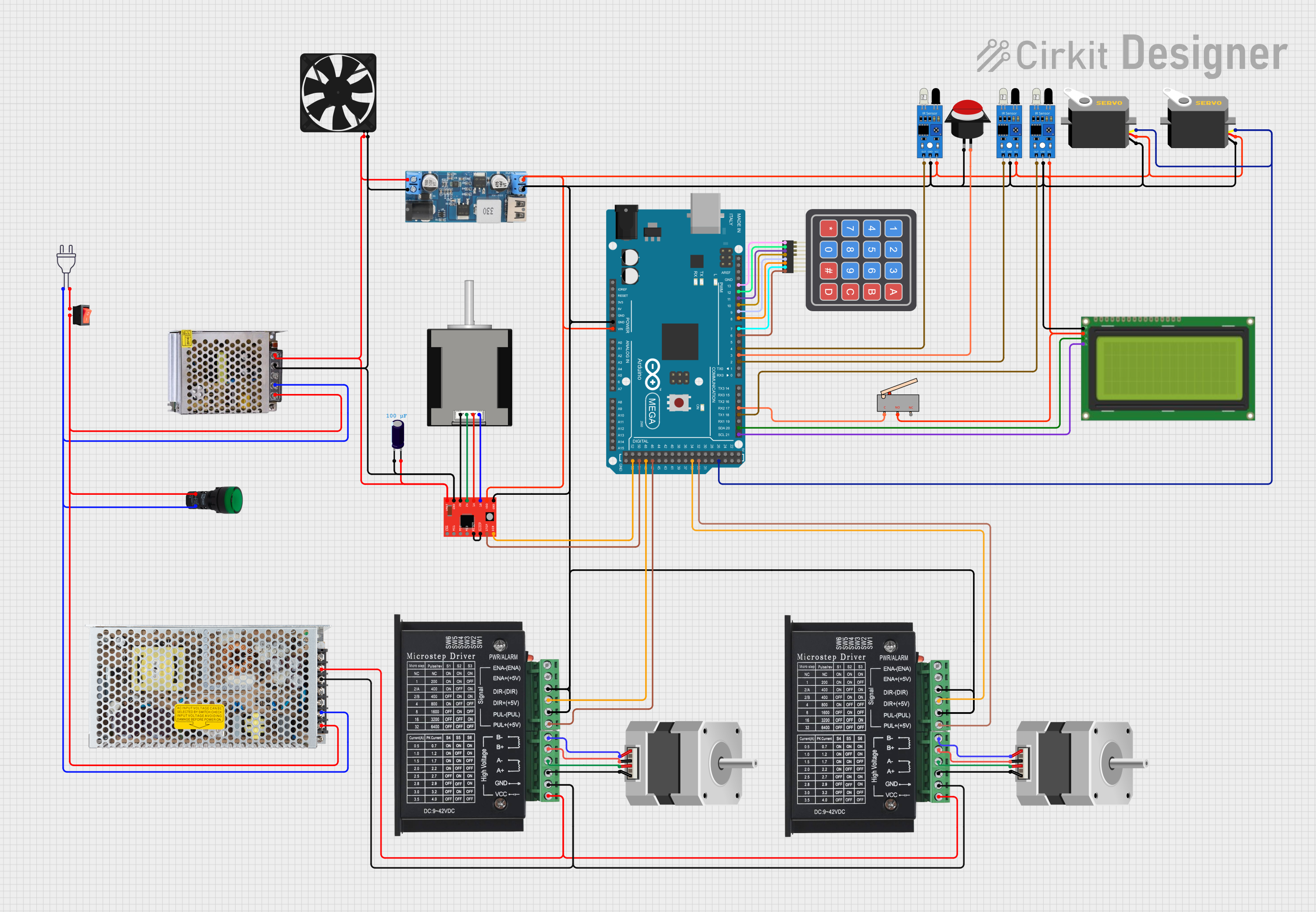 Open Project in Cirkit Designer
Explore Projects Built with Pololu 12V 4.5A DC-DC Step-Down Voltage Regulator
Open Project in Cirkit DesignerOpen Project in Cirkit DesignerOpen Project in Cirkit DesignerOpen Project in Cirkit DesignerCommon Applications
- Powering 12V devices from higher voltage sources (e.g., 24V or 36V batteries)
- Robotics and automation systems
- LED lighting systems
- Industrial control systems
- Portable electronics and embedded systems
Technical Specifications
Key Specifications
| Parameter | Value |
|---|---|
| Manufacturer | Pololu |
| Part Number | 12V 4.5A DC-DC Step-Down Voltage Regulator |
| Input Voltage Range | 15V to 38V |
| Output Voltage | 12V (fixed) |
| Maximum Output Current | 4.5A |
| Efficiency | Up to 95% |
| Switching Frequency | ~400 kHz |
| Operating Temperature | -40°C to +85°C |
| Dimensions | 25.4mm × 25.4mm × 12.7mm |
| Weight | 6.5g |
Pin Configuration
The Pololu 12V 4.5A DC-DC Step-Down Voltage Regulator has three main pins for connection:
| Pin Name | Description |
|---|---|
| VIN | Input voltage (15V to 38V) |
| GND | Ground (common for input and output) |
| VOUT | Regulated 12V output |
Usage Instructions
How to Use the Component in a Circuit
Connect the Input Voltage (VIN):
- Ensure the input voltage is within the range of 15V to 38V.
- Connect the positive terminal of the power source to the VIN pin.
- Connect the negative terminal of the power source to the GND pin.
Connect the Output Load:
- Connect the positive terminal of the load to the VOUT pin.
- Connect the negative terminal of the load to the GND pin.
Verify Connections:
- Double-check all connections to ensure proper polarity and secure wiring.
- Use appropriately rated wires to handle the current (up to 4.5A).
Power On:
- Turn on the input power source. The regulator will output a stable 12V to the connected load.
Important Considerations and Best Practices
- Heat Dissipation: At high currents, the regulator may generate heat. Ensure adequate ventilation or use a heatsink if necessary.
- Input Voltage Range: Do not exceed the maximum input voltage of 38V, as this may damage the regulator.
- Current Limitation: Ensure the connected load does not draw more than 4.5A to avoid overloading the regulator.
- Capacitors: For optimal performance, consider adding input and output capacitors close to the regulator to reduce noise and improve stability.
Example: Using with an Arduino UNO
The Pololu 12V 4.5A DC-DC Step-Down Voltage Regulator can be used to power an Arduino UNO and other peripherals. Below is an example circuit and code:
Circuit Setup
- Connect a 24V power source to the VIN and GND pins of the regulator.
- Connect the VOUT pin of the regulator to the VIN pin of the Arduino UNO.
- Connect the GND pin of the regulator to the GND pin of the Arduino UNO.
Example Code
// Example code to blink an LED connected to pin 13 of the Arduino UNO
// Ensure the Arduino is powered via the Pololu regulator's 12V output.

void setup() {
  pinMode(13, OUTPUT); // Set pin 13 as an output
}

void loop() {
  digitalWrite(13, HIGH); // Turn the LED on
  delay(1000);            // Wait for 1 second
  digitalWrite(13, LOW);  // Turn the LED off
  delay(1000);            // Wait for 1 second
}
Troubleshooting and FAQs
Common Issues and Solutions
No Output Voltage:
- Cause: Input voltage is below 15V or connections are incorrect.
- Solution: Verify the input voltage and ensure proper wiring.
Overheating:
- Cause: High current draw or insufficient ventilation.
- Solution: Reduce the load current or improve heat dissipation with a heatsink.
Output Voltage Fluctuations:
- Cause: Insufficient input or output capacitors.
- Solution: Add low-ESR capacitors (e.g., 100µF) close to the regulator.
Regulator Damage:
- Cause: Input voltage exceeds 38V or reverse polarity connection.
- Solution: Use a fuse and a diode for protection against overvoltage and reverse polarity.
FAQs
Q: Can this regulator be used with a 12V battery as the input?
A: No, the input voltage must be at least 15V. For a 12V battery, consider a boost regulator instead.
Q: Is the output voltage adjustable?
A: No, the output voltage is fixed at 12V.
Q: Can I use this regulator to power multiple devices?
A: Yes, as long as the total current draw does not exceed 4.5A.
Q: Does the regulator have built-in overcurrent protection?
A: Yes, the regulator includes overcurrent and thermal shutdown protection for safety.
This concludes the documentation for the Pololu 12V 4.5A DC-DC Step-Down Voltage Regulator.