How to Use digital potentionmeter: Examples, Pinouts, and Specs
Introduction
A digital potentiometer, often referred to as a "digipot," is an electronic component designed to emulate the analog function of a traditional potentiometer. It allows for the adjustment of resistance levels through digital signals, rather than mechanical movement. Digital potentiometers are widely used in applications where precise and programmable resistance settings are required, such as in volume control, calibration, and tuning circuits.
Explore Projects Built with digital potentionmeter
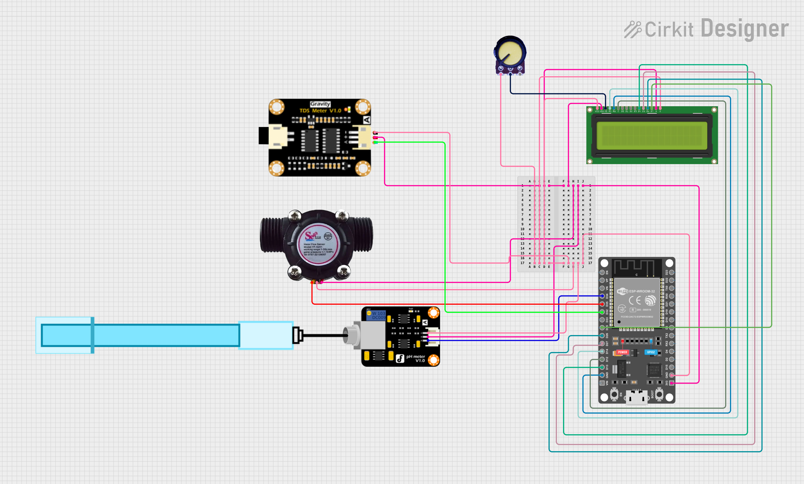
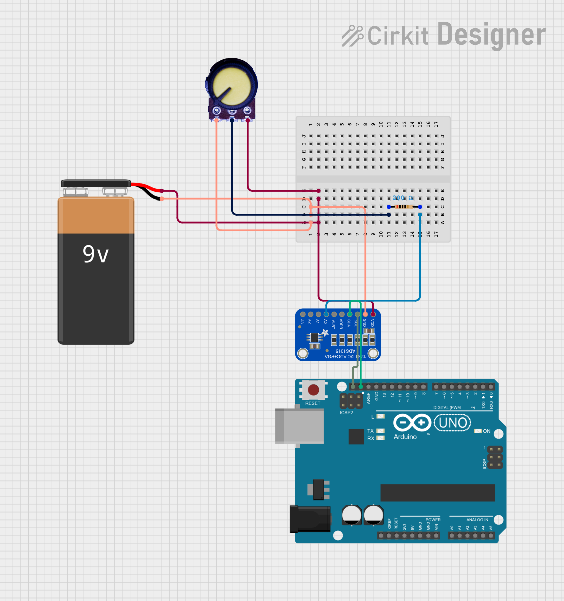
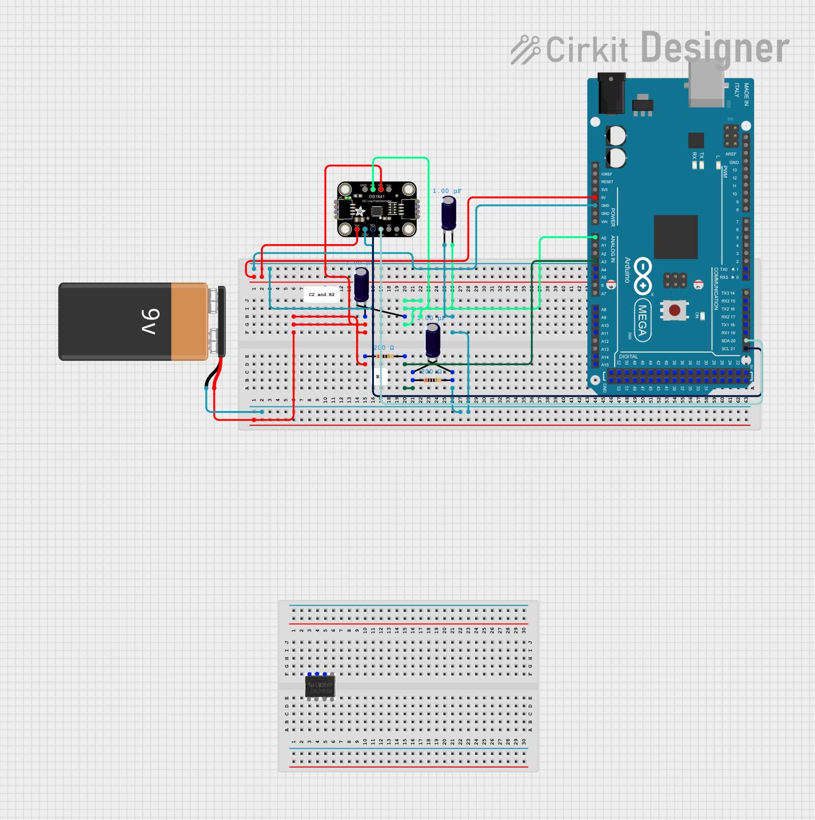
Explore Projects Built with digital potentionmeter
Technical Specifications
Key Technical Details
- Resistance Range: Typically from a few ohms to several megaohms
- Resolution: Number of steps or increments (e.g., 8-bit = 256 steps, 10-bit = 1024 steps)
- Supply Voltage: Usually ranges from 2.7V to 5.5V
- Tolerance: Variation in resistance, often ±20%
- Temperature Coefficient: Change in resistance with temperature
- Interface: SPI, I²C, or Up/Down control
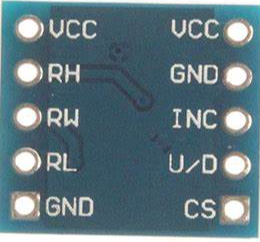
Pin Configuration and Descriptions
| Pin Number | Name | Description |
|---|---|---|
| 1 | VDD | Positive supply voltage |
| 2 | VSS | Ground reference |
| 3 | P0A | Terminal A of the potentiometer |
| 4 | P0W | Wiper terminal, connects to the variable resistor output |
| 5 | P0B | Terminal B of the potentiometer |
| 6 | CS | Chip Select for SPI communication |
| 7 | SCK | Serial Clock for SPI communication |
| 8 | SDI | Serial Data Input for SPI communication |
| 9 | SDO | Serial Data Output for SPI communication (optional) |
Note: The pin configuration may vary depending on the specific model of the digital potentiometer. Always refer to the manufacturer's datasheet for exact details.
Usage Instructions
How to Use the Component in a Circuit
- Power Supply: Connect VDD to a positive voltage within the specified range and VSS to ground.
- Potentiometer Terminals: Connect P0A and P0B across the circuit where variable resistance is needed. The wiper terminal P0W will provide the output.
- Digital Interface: Use the appropriate digital interface (SPI, I²C, or Up/Down) to control the resistance. For SPI, connect CS, SCK, and SDI to the controlling microcontroller.
Important Considerations and Best Practices
- Ensure that the voltage applied to the terminals does not exceed the maximum ratings.
- Avoid applying a high voltage differential directly across the wiper and either end terminal.
- Use proper decoupling capacitors close to the power supply pins to minimize noise.
- When using SPI, ensure that the CS pin is toggled correctly to enable and disable communication with the device.
Example Code for Arduino UNO
#include <SPI.h>

// Define the digital potentiometer control pins
const int CS_PIN = 10; // Chip Select pin

void setup() {
  // Set the CS pin as an output:
  pinMode(CS_PIN, OUTPUT);
  // Initialize SPI:
  SPI.begin();
}

void loop() {
  // Set the digital potentiometer to mid-scale
  setPotWiper(128);
  delay(1000);
}

// Function to set the wiper position
void setPotWiper(int value) {
  // Take the CS pin low to select the device:
  digitalWrite(CS_PIN, LOW);
  // Send the command byte and value (two bytes)
  SPI.transfer(0x11); // Command byte for potentiometer 0
  SPI.transfer(value); // Wiper value
  // Take the CS pin high to de-select the device:
  digitalWrite(CS_PIN, HIGH);
}
Note: The command byte 0x11 is an example and may differ based on the digital potentiometer's datasheet.
Troubleshooting and FAQs
Common Issues
- Incorrect Resistance Values: Ensure that the digital potentiometer is not exposed to voltages outside its operating range and that the correct command sequence is used.
- Communication Errors: Verify that the SPI or I²C connections are secure and that the correct protocol and speed are being used.
- Noisy Output: Check for proper decoupling and that the power supply is stable and within the specified range.
Solutions and Tips for Troubleshooting
- Double-check wiring against the datasheet's pin configuration.
- Use oscilloscope or logic analyzer to confirm correct digital communication.
- Ensure that the microcontroller's voltage levels are compatible with the digital potentiometer's logic level requirements.
FAQs
Q: Can I use a digital potentiometer to control high-power applications? A: Digital potentiometers are not designed for high-power applications. They are intended for low-current, signal-level adjustments.
Q: How do I reset the wiper position after power loss? A: Most digital potentiometers do not retain their position after power loss. You will need to initialize the wiper position in your setup code.
Q: Is it possible to daisy-chain multiple digital potentiometers? A: Yes, many digital potentiometers support daisy-chaining through SPI. Check the datasheet for specific instructions.
Remember to always consult the specific datasheet for your digital potentiometer model for the most accurate and detailed information.