How to Use Break Beam emitter: Examples, Pinouts, and Specs

Introduction
The Break Beam Emitter (Manufacturer Part ID: 2168) by Adafruit Industries is a sensor that emits a beam of infrared light. This beam, when paired with a compatible receiver, can detect interruptions caused by objects passing through it. The emitter is a key component in break beam systems, which are widely used for object detection, counting, and safety mechanisms.
Explore Projects Built with Break Beam emitter
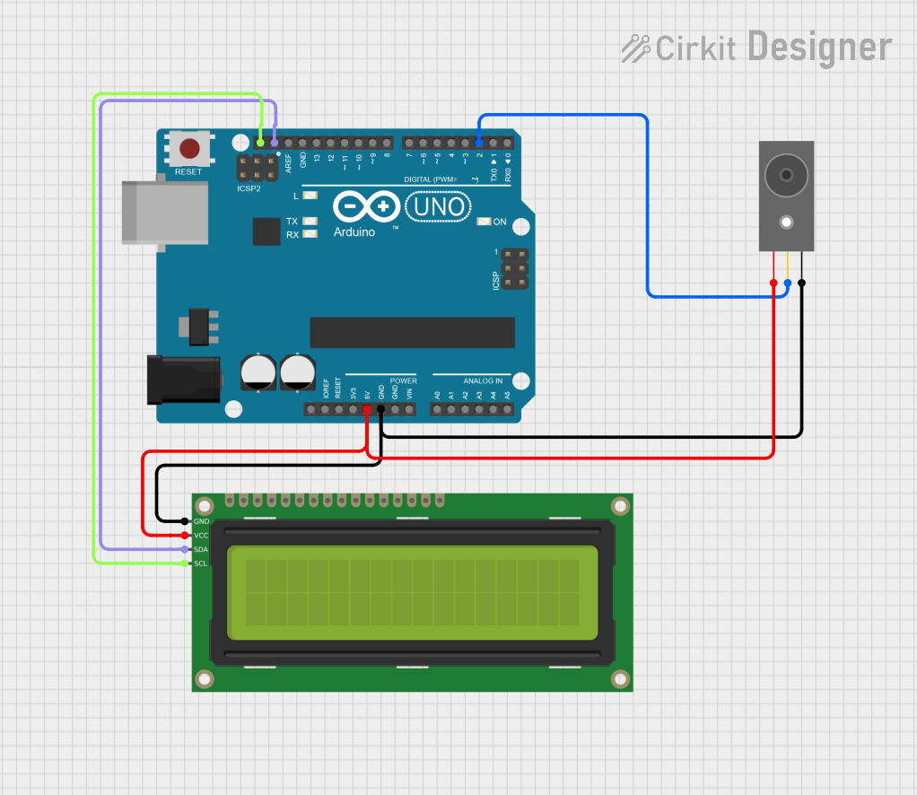

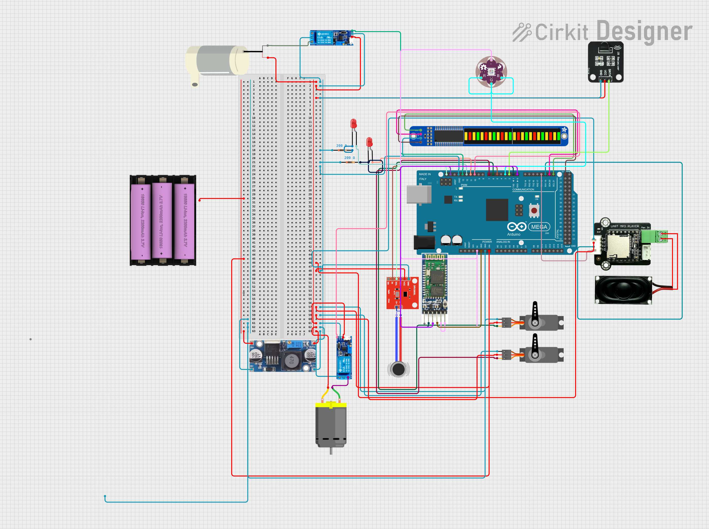

Explore Projects Built with Break Beam emitter
Common Applications
- Object detection in automation systems
- Counting items on conveyor belts
- Security systems (e.g., detecting intrusions)
- Safety mechanisms in industrial equipment
- Interactive installations and robotics
Technical Specifications
The following table outlines the key technical details of the Break Beam Emitter:
| Parameter | Value |
|---|---|
| Operating Voltage | 3.3V to 5V |
| Current Consumption | ~20mA |
| Wavelength | Infrared (typically 940nm) |
| Beam Range | Up to 50cm (depending on receiver) |
| Dimensions | 10mm x 10mm x 30mm |
| Operating Temperature | -25°C to 85°C |
Pin Configuration
The Break Beam Emitter has two pins for connection. The table below describes the pinout:
| Pin | Name | Description |
|---|---|---|
| 1 | VCC | Power supply input (3.3V to 5V) |
| 2 | GND | Ground connection |
Usage Instructions
How to Use the Break Beam Emitter in a Circuit
- Power the Emitter: Connect the
VCCpin to a 3.3V or 5V power source and theGNDpin to the ground of your circuit. - Pair with a Receiver: The emitter must be aligned with a compatible infrared receiver. Ensure the beam path is unobstructed for proper operation.
- Mounting: Secure the emitter and receiver in fixed positions to maintain alignment. Use brackets or enclosures if necessary.
- Testing: Power the circuit and verify that the receiver detects the beam. Interrupt the beam with an object to confirm detection.
Important Considerations
- Alignment: Proper alignment between the emitter and receiver is critical for reliable operation.
- Power Supply: Ensure a stable power supply to avoid fluctuations in the infrared beam intensity.
- Environmental Factors: Avoid direct sunlight or strong ambient infrared sources, as these can interfere with the beam.
- Distance: The effective range depends on the receiver's sensitivity. Test the setup to determine the maximum reliable distance.
Example: Using with an Arduino UNO
Below is an example of how to use the Break Beam Emitter with a compatible receiver and an Arduino UNO to detect beam interruptions:
// Example code for using a Break Beam Emitter with an Arduino UNO
// This code assumes a compatible receiver is connected to pin 2 of the Arduino

#define RECEIVER_PIN 2  // Digital pin connected to the receiver output

void setup() {
  pinMode(RECEIVER_PIN, INPUT);  // Set the receiver pin as input
  Serial.begin(9600);           // Initialize serial communication
  Serial.println("Break Beam Sensor Test");
}

void loop() {
  int beamStatus = digitalRead(RECEIVER_PIN);  // Read the receiver's output

  if (beamStatus == HIGH) {
    // Beam is uninterrupted
    Serial.println("Beam is clear");
  } else {
    // Beam is interrupted
    Serial.println("Beam interrupted!");
  }

  delay(100);  // Small delay for stability
}
Notes:
- Connect the receiver's output pin to the Arduino's
RECEIVER_PIN(pin 2 in this example). - Ensure the emitter and receiver are properly aligned for accurate detection.
Troubleshooting and FAQs
Common Issues and Solutions
The receiver does not detect the beam:
- Check the alignment between the emitter and receiver.
- Verify the power supply to the emitter (3.3V to 5V).
- Ensure there are no obstructions in the beam path.
False detections or inconsistent operation:
- Minimize ambient infrared interference (e.g., sunlight or nearby IR sources).
- Use shielding or enclosures to block external light sources.
Short detection range:
- Verify the receiver's sensitivity and ensure the emitter is operating at the correct voltage.
- Clean the emitter and receiver lenses to remove dust or dirt.
The emitter gets warm:
- Check the power supply voltage and current. Ensure it does not exceed the specified limits.
FAQs
Q: Can I use the Break Beam Emitter with a different receiver?
A: Yes, as long as the receiver is compatible with the emitter's wavelength (typically 940nm) and operating range.
Q: What is the maximum range of the emitter?
A: The range depends on the receiver's sensitivity and environmental conditions. Typically, it can reach up to 50cm.
Q: Can I use multiple emitters in the same system?
A: Yes, but ensure that the beams do not interfere with each other. Use physical separation or modulation techniques to avoid cross-talk.
Q: Is the emitter waterproof?
A: No, the emitter is not waterproof. Use appropriate enclosures for outdoor or wet environments.
This documentation provides a comprehensive guide to using the Adafruit Break Beam Emitter (Part ID: 2168). For further assistance, refer to Adafruit's official resources or community forums.