How to Use PCM5102A: Examples, Pinouts, and Specs
Introduction
The PCM5102A, manufactured by Texas Instruments, is a high-performance digital-to-analog converter (DAC) designed specifically for audio applications. It supports 32-bit audio processing and delivers exceptional audio quality with low distortion and a high signal-to-noise ratio (SNR). This makes it an excellent choice for high-fidelity audio systems, including home audio equipment, professional audio devices, and portable audio players.
Explore Projects Built with PCM5102A


Explore Projects Built with PCM5102A
Common Applications and Use Cases
- High-fidelity home audio systems
- Professional audio equipment
- Portable music players
- Audio interfaces and sound cards
- Digital audio streaming devices
- Automotive audio systems
Technical Specifications
Key Technical Details
- Audio Resolution: Up to 32-bit
- Sampling Rate: Supports up to 384 kHz
- Signal-to-Noise Ratio (SNR): 112 dB
- Total Harmonic Distortion + Noise (THD+N): -93 dB
- Output Voltage: 2.1 Vrms (typical)
- Power Supply Voltage:
- Analog: 3.3 V
- Digital: 1.8 V to 3.3 V
- Power Consumption: Low-power operation with 20 mW (typical)
- Interface: I2S (Inter-IC Sound) for digital audio input
- Package: 20-pin TSSOP (Thin Shrink Small Outline Package)
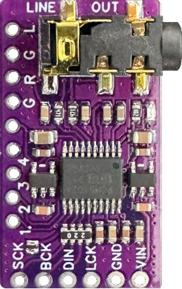
Pin Configuration and Descriptions
The PCM5102A comes in a 20-pin TSSOP package. Below is the pin configuration and description:
| Pin Number | Pin Name | Type | Description |
|---|---|---|---|
| 1 | DVDD | Power | Digital power supply (1.8 V to 3.3 V). |
| 2 | DGND | Ground | Digital ground. |
| 3 | SCK | Input | System clock input for audio data. |
| 4 | BCK | Input | Bit clock input for I2S interface. |
| 5 | DIN | Input | Digital audio data input (I2S format). |
| 6 | LRCK | Input | Left-right clock input for I2S interface. |
| 7 | FMT | Input | Audio format selection pin. |
| 8 | XSMT | Input | Soft mute control pin. |
| 9 | FLT | Input | Filter response selection pin. |
| 10 | NC | - | No connection. |
| 11 | VCOM | Output | Common-mode voltage output. |
| 12 | VOUTL | Output | Left-channel analog audio output. |
| 13 | VOUTR | Output | Right-channel analog audio output. |
| 14 | AGND | Ground | Analog ground. |
| 15 | AVDD | Power | Analog power supply (3.3 V). |
| 16 | NC | - | No connection. |
| 17 | FMT1 | Input | Audio format selection pin (used with FMT). |
| 18 | SCL | Input | I2C clock input (optional, for advanced configurations). |
| 19 | SDA | Input/Output | I2C data line (optional, for advanced configurations). |
| 20 | RESET | Input | Active-low reset pin. |
Usage Instructions
How to Use the PCM5102A in a Circuit
- Power Supply: Connect the analog power supply (AVDD) to 3.3 V and the digital power supply (DVDD) to 1.8 V or 3.3 V. Ensure proper decoupling capacitors are placed close to the power pins.
- Grounding: Connect AGND and DGND to a common ground plane to minimize noise.
- I2S Interface: Connect the I2S signals (SCK, BCK, DIN, LRCK) to the corresponding pins of your microcontroller or audio source.
- Audio Output: Use the VOUTL and VOUTR pins to connect to an amplifier or headphones. Add appropriate filtering capacitors if needed.
- Audio Format: Configure the FMT and FMT1 pins to select the desired audio format (e.g., I2S, left-justified, or right-justified).
- Reset: Use the RESET pin to initialize the DAC during power-up or after a fault condition.
Important Considerations and Best Practices
- Clocking: Ensure the system clock (SCK) is stable and matches the required frequency for the selected sampling rate.
- Decoupling: Use low-ESR capacitors for power supply decoupling to reduce noise and improve performance.
- PCB Layout: Keep the analog and digital ground planes separate but connected at a single point to minimize interference.
- Soft Mute: Use the XSMT pin to enable soft mute functionality, which prevents audible pops during power-up or shutdown.
- Filter Selection: Use the FLT pin to select the desired digital filter response for your application.
Example: Connecting PCM5102A to Arduino UNO
The PCM5102A can be connected to an Arduino UNO using the I2S interface. However, since the Arduino UNO does not natively support I2S, you may need an external I2S interface module or use a microcontroller with built-in I2S support (e.g., ESP32).
Here is an example code snippet for an ESP32:
#include <driver/i2s.h>

// I2S configuration for PCM5102A
#define I2S_NUM         I2S_NUM_0  // Use I2S0 peripheral
#define I2S_BCK_PIN     26         // Bit clock pin
#define I2S_LRCK_PIN    25         // Left-right clock pin
#define I2S_DATA_PIN    22         // Data output pin

void setup() {
  // Configure I2S peripheral
  i2s_config_t i2s_config = {
    .mode = (i2s_mode_t)(I2S_MODE_MASTER | I2S_MODE_TX), // Master TX mode
    .sample_rate = 44100,                               // Sampling rate
    .bits_per_sample = I2S_BITS_PER_SAMPLE_16BIT,       // 16-bit audio
    .channel_format = I2S_CHANNEL_FMT_RIGHT_LEFT,       // Stereo format
    .communication_format = I2S_COMM_FORMAT_I2S,       // I2S standard
    .intr_alloc_flags = 0,                              // Default interrupt
    .dma_buf_count = 8,                                 // Number of DMA buffers
    .dma_buf_len = 64                                   // Size of each buffer
  };

  // Configure I2S pins
  i2s_pin_config_t pin_config = {
    .bck_io_num = I2S_BCK_PIN,
    .ws_io_num = I2S_LRCK_PIN,
    .data_out_num = I2S_DATA_PIN,
    .data_in_num = I2S_PIN_NO_CHANGE // Not used
  };

  // Install and start I2S driver
  i2s_driver_install(I2S_NUM, &i2s_config, 0, NULL);
  i2s_set_pin(I2S_NUM, &pin_config);
}

void loop() {
  // Example: Send a sine wave to the DAC
  static const int amplitude = 10000;
  static const int frequency = 440; // 440 Hz (A4 note)
  static const int sample_rate = 44100;
  static int sample = 0;

  int16_t sample_data = amplitude * sin(2 * PI * frequency * sample / sample_rate);
  i2s_write(I2S_NUM, &sample_data, sizeof(sample_data), NULL, portMAX_DELAY);

  sample = (sample + 1) % sample_rate;
}
Troubleshooting and FAQs
Common Issues and Solutions
No Audio Output:
- Verify that the power supply voltages (AVDD and DVDD) are correct and stable.
- Check the I2S connections and ensure the audio source is configured correctly.
- Ensure the RESET pin is not held low.
Distorted Audio:
- Verify the sampling rate and bit depth match the audio source.
- Check for noise or interference in the power supply or ground connections.
- Ensure proper decoupling capacitors are used.
Popping Sounds:
- Use the XSMT pin to enable soft mute during power-up or shutdown.
- Avoid abrupt changes in the audio signal.
High Noise Floor:
- Ensure the analog and digital ground planes are properly separated and connected at a single point.
- Minimize the length of signal traces to reduce noise pickup.
FAQs
Q: Can the PCM5102A operate without an external clock?
A: No, the PCM5102A requires a stable