How to Use mcp2551: Examples, Pinouts, and Specs
Introduction
The MCP2551 is a high-speed CAN (Controller Area Network) transceiver manufactured by Analog. It serves as the interface between a CAN protocol controller and the physical CAN bus, enabling robust communication in automotive and industrial environments. The MCP2551 is designed to support data rates of up to 1 Mbps, making it suitable for high-speed applications. Its low power consumption, high noise immunity, and fault-tolerant design make it a reliable choice for demanding applications.
Explore Projects Built with mcp2551
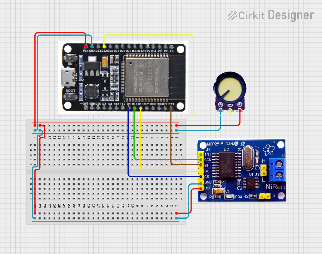

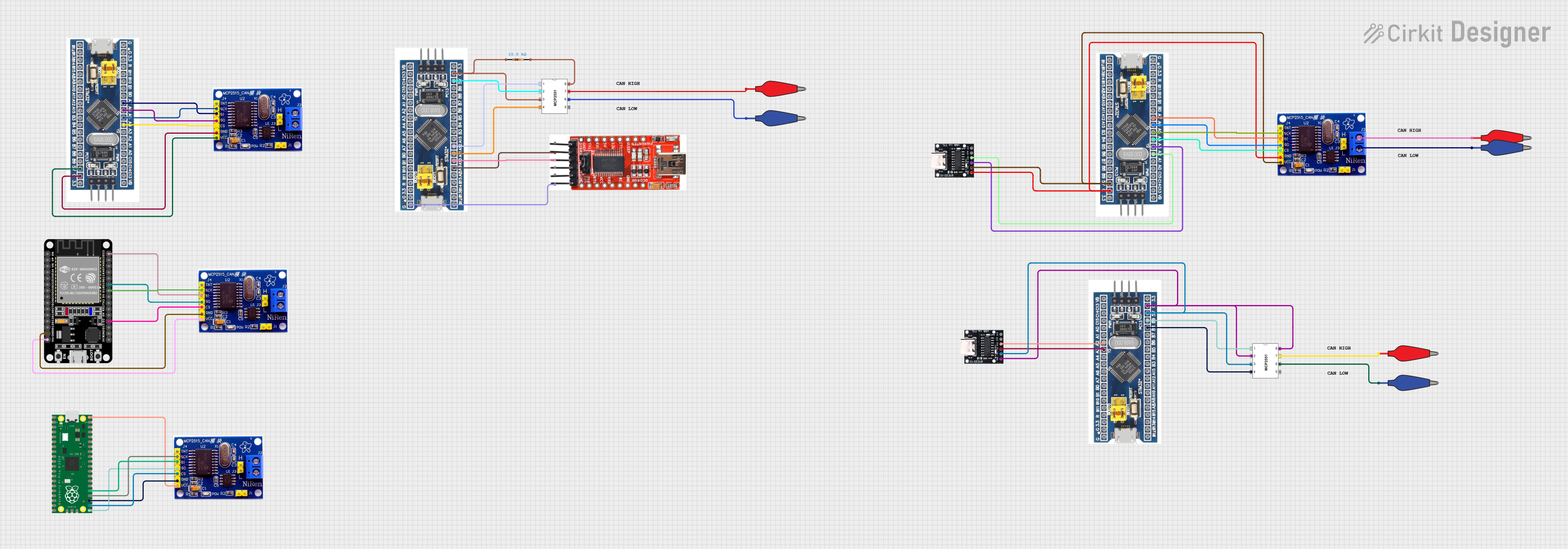
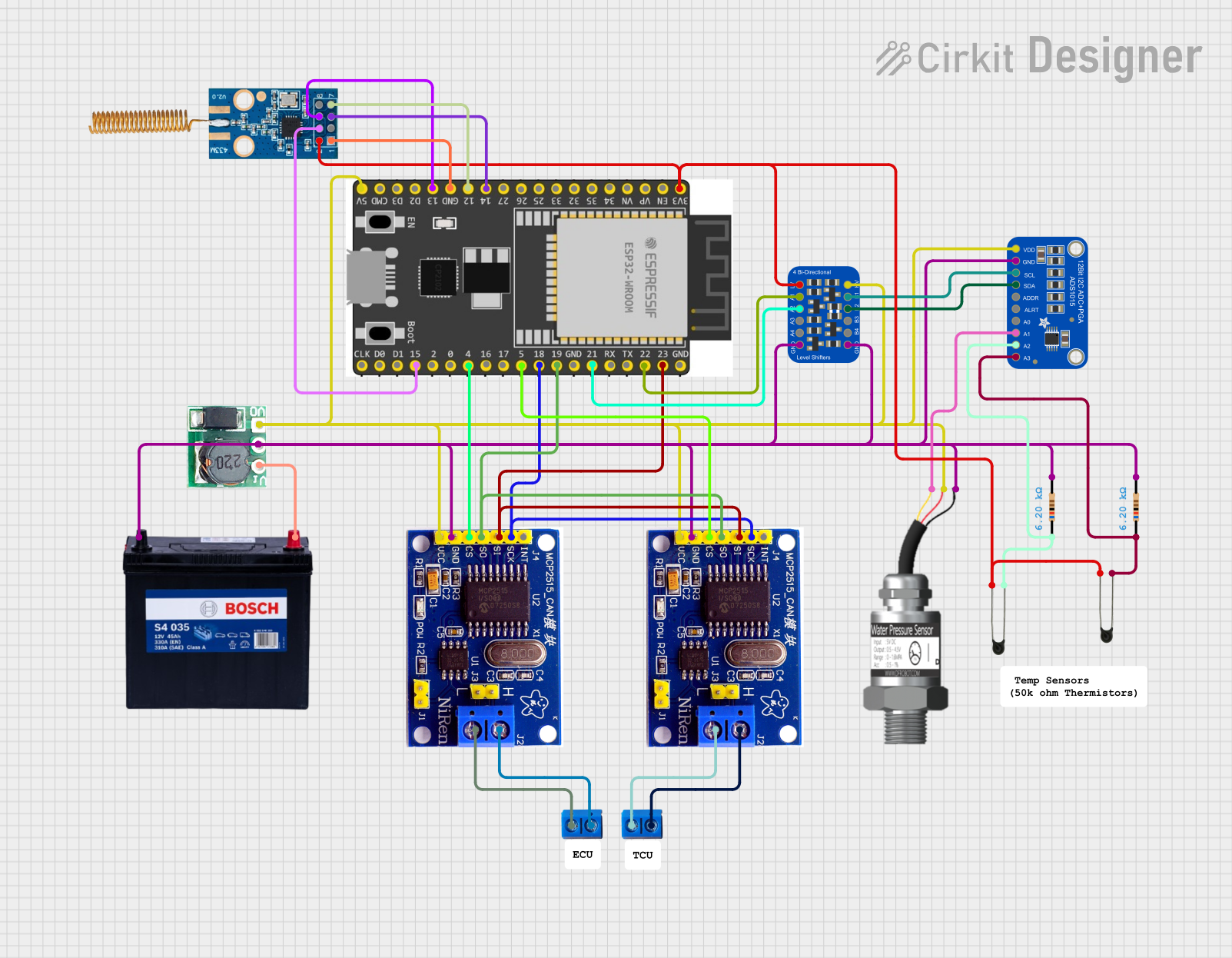
Explore Projects Built with mcp2551
Common Applications and Use Cases
- Automotive systems (e.g., engine control units, body control modules)
- Industrial automation and control
- Building automation systems
- Medical equipment
- Robotics and embedded systems requiring CAN communication
Technical Specifications
Key Technical Details
- Supply Voltage (VDD): 4.5V to 5.5V
- Data Rate: Up to 1 Mbps
- Bus Voltage Range: -7V to +12V
- Standby Current: 1 µA (typical)
- Operating Temperature Range: -40°C to +125°C
- ESD Protection: ±4 kV (Human Body Model)
- Propagation Delay (High-Speed Mode): 120 ns (typical)
- Package Options: PDIP, SOIC, and others
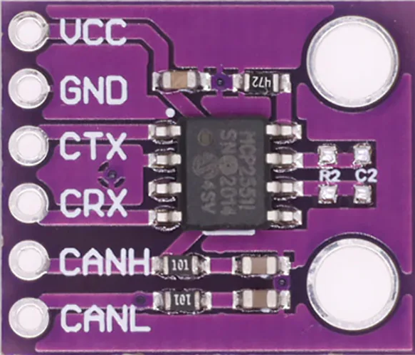
Pin Configuration and Descriptions
The MCP2551 is typically available in an 8-pin package. Below is the pinout and description:
| Pin Number | Pin Name | Description |
|---|---|---|
| 1 | TXD | Transmit Data Input: Connected to the CAN controller's transmit output. |
| 2 | VSS | Ground: Connect to system ground. |
| 3 | VDD | Supply Voltage: Connect to a 5V power supply. |
| 4 | RXD | Receive Data Output: Outputs data received from the CAN bus. |
| 5 | VREF | Reference Voltage Output: Provides a reference voltage (typically 2.5V). |
| 6 | CANL | CAN Low: Connect to the CAN bus low line. |
| 7 | CANH | CAN High: Connect to the CAN bus high line. |
| 8 | RS | Slope Control Input: Controls the slew rate of the CAN signals. |
Usage Instructions
How to Use the MCP2551 in a Circuit
Power Supply:
- Connect the VDD pin to a regulated 5V power supply.
- Connect the VSS pin to the system ground.
CAN Bus Connection:
- Connect the CANH and CANL pins to the CAN bus lines.
- Use a 120-ohm termination resistor between CANH and CANL at each end of the bus.
Controller Interface:
- Connect the TXD pin to the CAN controller's transmit output.
- Connect the RXD pin to the CAN controller's receive input.
Slope Control:
- Use the RS pin to control the slew rate of the CAN signals. For high-speed operation, connect RS to ground. For reduced EMI, connect RS to a resistor to ground.
Reference Voltage:
- The VREF pin provides a reference voltage (typically 2.5V) that can be used for external circuits if needed.
Important Considerations and Best Practices
- Ensure proper decoupling by placing a 0.1 µF ceramic capacitor close to the VDD pin.
- Use twisted-pair cables for the CANH and CANL lines to minimize noise and improve signal integrity.
- Avoid long stubs on the CAN bus to reduce signal reflections.
- Ensure the total bus length and node count comply with the CAN standard for the desired data rate.
Example: Connecting MCP2551 to an Arduino UNO
Below is an example of how to connect the MCP2551 to an Arduino UNO for CAN communication:
Circuit Connections
- MCP2551 TXD → Arduino Digital Pin 10 (CAN Controller TX)
- MCP2551 RXD → Arduino Digital Pin 11 (CAN Controller RX)
- MCP2551 CANH → CAN Bus High Line
- MCP2551 CANL → CAN Bus Low Line
- MCP2551 VDD → 5V
- MCP2551 VSS → GND
- MCP2551 RS → GND (for high-speed mode)
Arduino Code Example
#include <SPI.h>
#include <mcp2515.h> // Include the MCP2515 CAN controller library

struct can_frame canMsg; // Define a CAN message structure
MCP2515 mcp2515(10);     // Initialize MCP2515 with CS pin 10

void setup() {
  Serial.begin(9600);
  mcp2515.reset();       // Reset the MCP2515
  mcp2515.setBitrate(CAN_500KBPS); // Set CAN bus speed to 500 kbps
  mcp2515.setNormalMode(); // Set MCP2515 to normal mode
  Serial.println("MCP2551 CAN Transceiver Initialized");
}

void loop() {
  // Example: Sending a CAN message
  canMsg.can_id = 0x100; // Set CAN ID
  canMsg.can_dlc = 2;    // Set data length (2 bytes)
  canMsg.data[0] = 0x55; // First byte of data
  canMsg.data[1] = 0xAA; // Second byte of data

  if (mcp2515.sendMessage(&canMsg) == MCP2515::ERROR_OK) {
    Serial.println("Message Sent Successfully");
  } else {
    Serial.println("Error Sending Message");
  }

  delay(1000); // Wait 1 second before sending the next message
}
Troubleshooting and FAQs
Common Issues and Solutions
No Communication on the CAN Bus:
- Verify that the CANH and CANL lines are properly connected and terminated with 120-ohm resistors at both ends of the bus.
- Ensure the MCP2551 is powered correctly (5V on VDD and GND on VSS).
- Check the TXD and RXD connections between the MCP2551 and the CAN controller.
High Error Rate or Noise on the Bus:
- Use twisted-pair cables for the CANH and CANL lines to reduce noise.
- Ensure the RS pin is configured correctly for the desired slew rate.
MCP2551 Overheating:
- Check for short circuits on the CANH and CANL lines.
- Ensure the bus voltage does not exceed the specified range (-7V to +12V).
FAQs
Q: Can the MCP2551 operate at 3.3V?
A: No, the MCP2551 requires a supply voltage of 4.5V to 5.5V. For 3.3V systems, consider using a level shifter or a different transceiver designed for 3.3V operation.
Q: What is the maximum number of nodes supported on the CAN bus?
A: The maximum number of nodes depends on the bus length, data rate, and transceiver characteristics. Typically, up to 120 nodes can be supported.
Q: How do I reduce EMI in my design?
A: Use the RS pin to control the slew rate of the CAN signals. Adding a resistor between RS and ground can reduce EMI by slowing down the signal transitions.