How to Use esp32-WROOM: Examples, Pinouts, and Specs
Introduction
The ESP32-WROOM is a powerful microcontroller module designed for Internet of Things (IoT) applications. It features integrated Wi-Fi and Bluetooth capabilities, a dual-core processor, and a wide range of GPIO pins. This module is highly versatile and supports various communication protocols, making it suitable for embedded systems, smart home devices, wearables, and industrial automation.
Explore Projects Built with esp32-WROOM


Explore Projects Built with esp32-WROOM
Common Applications and Use Cases
- IoT devices and smart home automation
- Wireless sensor networks
- Wearable technology
- Industrial control systems
- Robotics and drones
- Prototyping and development of connected devices
Technical Specifications
The ESP32-WROOM module is packed with features that make it a robust choice for IoT and embedded applications. Below are its key technical specifications:
| Specification | Details |
|---|---|
| Microcontroller | Dual-core Xtensa® 32-bit LX6 processor |
| Clock Speed | Up to 240 MHz |
| Flash Memory | 4 MB (default, varies by model) |
| SRAM | 520 KB |
| Wireless Connectivity | Wi-Fi 802.11 b/g/n, Bluetooth v4.2 + BLE |
| Operating Voltage | 3.0V to 3.6V |
| GPIO Pins | 34 (multipurpose, including ADC, DAC, PWM, I2C, SPI, UART, etc.) |
| ADC Channels | 18 (12-bit resolution) |
| DAC Channels | 2 |
| Communication Protocols | UART, SPI, I2C, I2S, CAN, PWM, SDIO |
| Power Consumption | Ultra-low power consumption in deep sleep mode (as low as 10 µA) |
| Operating Temperature | -40°C to 85°C |
| Dimensions | 18 mm x 25.5 mm x 3.1 mm |
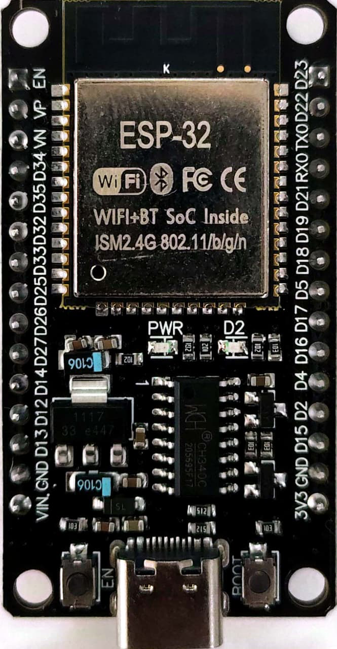
Pin Configuration and Descriptions
The ESP32-WROOM module has a total of 38 pins. Below is a table describing the key pins and their functions:
| Pin Name | Type | Description |
|---|---|---|
| GND | Power | Ground pin |
| 3V3 | Power | 3.3V power supply input |
| EN | Input | Enable pin (active high, used to reset the module) |
| IO0 | GPIO/Boot Mode | GPIO0, also used to enter bootloader mode during programming |
| IO2 | GPIO | General-purpose I/O pin |
| IO4 | GPIO | General-purpose I/O pin |
| IO12 | GPIO/ADC/DAC | GPIO12, can also function as ADC or DAC |
| IO13 | GPIO/ADC | GPIO13, can also function as ADC |
| IO14 | GPIO/PWM | GPIO14, supports PWM output |
| IO15 | GPIO/PWM | GPIO15, supports PWM output |
| IO16 | GPIO | General-purpose I/O pin |
| IO17 | GPIO | General-purpose I/O pin |
| IO18 | GPIO/SPI | GPIO18, supports SPI communication |
| IO19 | GPIO/SPI | GPIO19, supports SPI communication |
| IO21 | GPIO/I2C | GPIO21, supports I2C communication (SDA) |
| IO22 | GPIO/I2C | GPIO22, supports I2C communication (SCL) |
| IO23 | GPIO/SPI | GPIO23, supports SPI communication |
| IO25 | GPIO/DAC | GPIO25, can also function as DAC |
| IO26 | GPIO/DAC | GPIO26, can also function as DAC |
| IO27 | GPIO/ADC | GPIO27, can also function as ADC |
| IO32 | GPIO/ADC | GPIO32, can also function as ADC |
| IO33 | GPIO/ADC | GPIO33, can also function as ADC |
| IO34 | GPIO/ADC | GPIO34, input-only ADC pin |
| IO35 | GPIO/ADC | GPIO35, input-only ADC pin |
Usage Instructions
How to Use the ESP32-WROOM in a Circuit
- Power Supply: Provide a stable 3.3V power supply to the
3V3pin. Ensure the current supply is sufficient for the module's operation. - Boot Mode: To upload code, connect GPIO0 to GND and reset the module. After uploading, disconnect GPIO0 from GND.
- Programming: Use a USB-to-serial adapter to connect the ESP32-WROOM to your computer. Common connections:
- TXD (adapter) → RXD (ESP32)
- RXD (adapter) → TXD (ESP32)
- GND (adapter) → GND (ESP32)
- 3.3V (adapter) → 3V3 (ESP32)
- GPIO Usage: Configure GPIO pins in your code for input, output, or communication protocols as needed.
Important Considerations and Best Practices
- Voltage Levels: Ensure all input signals to the GPIO pins are within the 3.3V range to avoid damage.
- Deep Sleep Mode: Use deep sleep mode to minimize power consumption in battery-powered applications.
- Antenna Placement: Ensure the onboard antenna has sufficient clearance from metal objects to avoid interference.
- Heat Management: Avoid enclosing the module in a space with poor ventilation, as it may generate heat during operation.
Example Code for Arduino UNO Integration
Below is an example of using the ESP32-WROOM with the Arduino IDE to blink an LED:
// Example: Blink an LED connected to GPIO2 on the ESP32-WROOM

#define LED_PIN 2  // GPIO2 is connected to the onboard LED

void setup() {
  pinMode(LED_PIN, OUTPUT);  // Set GPIO2 as an output pin
}

void loop() {
  digitalWrite(LED_PIN, HIGH);  // Turn the LED on
  delay(1000);                  // Wait for 1 second
  digitalWrite(LED_PIN, LOW);   // Turn the LED off
  delay(1000);                  // Wait for 1 second
}
Troubleshooting and FAQs
Common Issues and Solutions
ESP32-WROOM Not Responding
- Cause: Incorrect wiring or insufficient power supply.
- Solution: Double-check all connections and ensure a stable 3.3V power supply.
Code Upload Fails
- Cause: GPIO0 is not connected to GND during programming.
- Solution: Connect GPIO0 to GND, reset the module, and try uploading again.
Wi-Fi Connection Issues
- Cause: Incorrect SSID or password.
- Solution: Verify the Wi-Fi credentials in your code and ensure the network is within range.
Bluetooth Not Discoverable
- Cause: Bluetooth not initialized in the code.
- Solution: Ensure the Bluetooth library is included and properly configured in your code.
FAQs
Q: Can the ESP32-WROOM operate on 5V?
A: No, the ESP32-WROOM operates on 3.3V. Applying 5V to its pins may damage the module.Q: How do I reset the ESP32-WROOM?
A: Press theENpin or connect it momentarily to GND to reset the module.Q: Can I use the ESP32-WROOM for battery-powered applications?
A: Yes, the ESP32-WROOM is ideal for battery-powered applications due to its low-power modes.Q: What is the maximum range of the Wi-Fi module?
A: The Wi-Fi range depends on the environment but typically extends up to 100 meters in open space.
This documentation provides a comprehensive guide to using the ESP32-WROOM module effectively.