How to Use ULN 2003: Examples, Pinouts, and Specs
Introduction
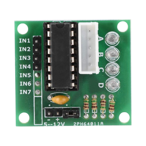
The ULN2003 Stepper Motor Driver Module is an integrated circuit designed for driving stepper motors, particularly in applications requiring high-voltage and high-current control. It is composed of seven NPN Darlington pairs, allowing it to interface directly with many microcontrollers, such as the Arduino UNO. The common-cathode clamp diodes provide protection against inductive kickback when driving inductive loads. This module is widely used in DIY projects, robotics, and industrial applications for controlling stepper motors.
Explore Projects Built with ULN 2003

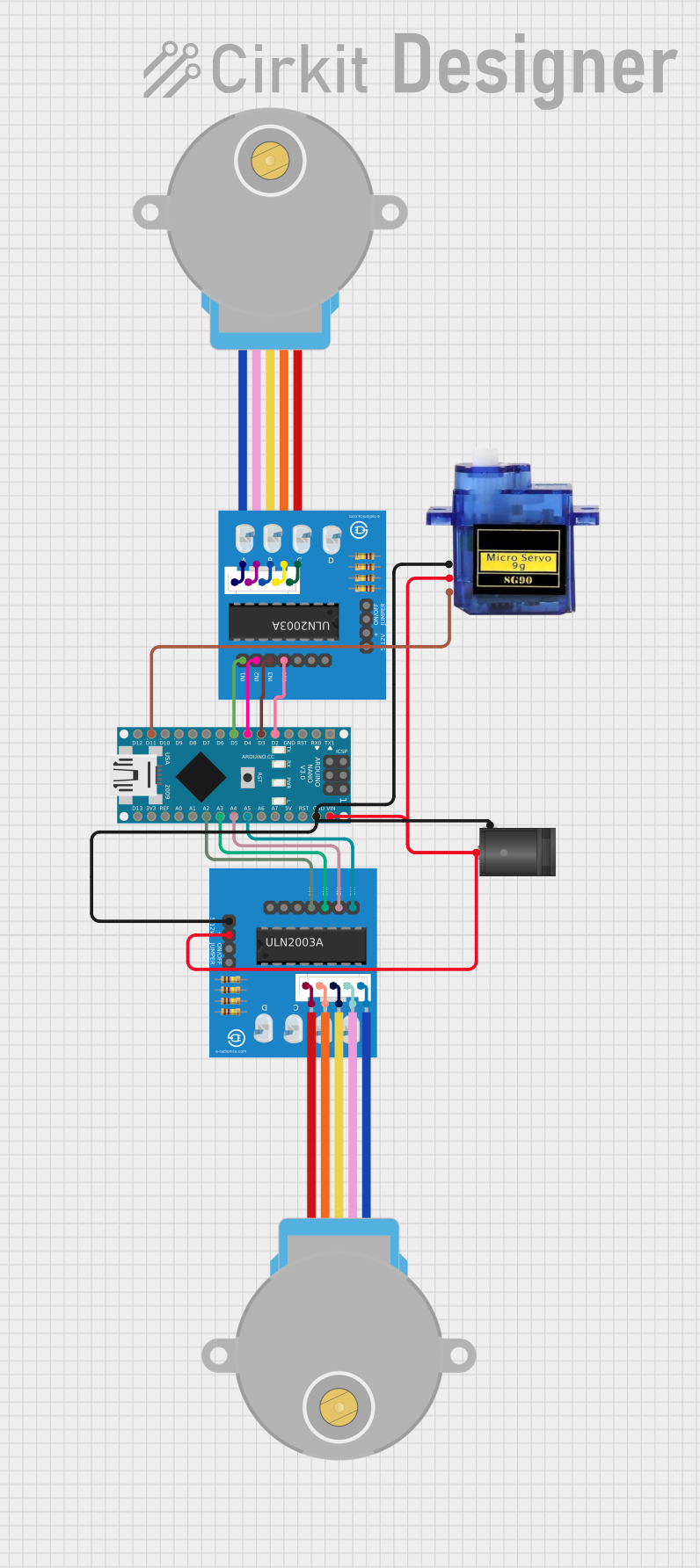
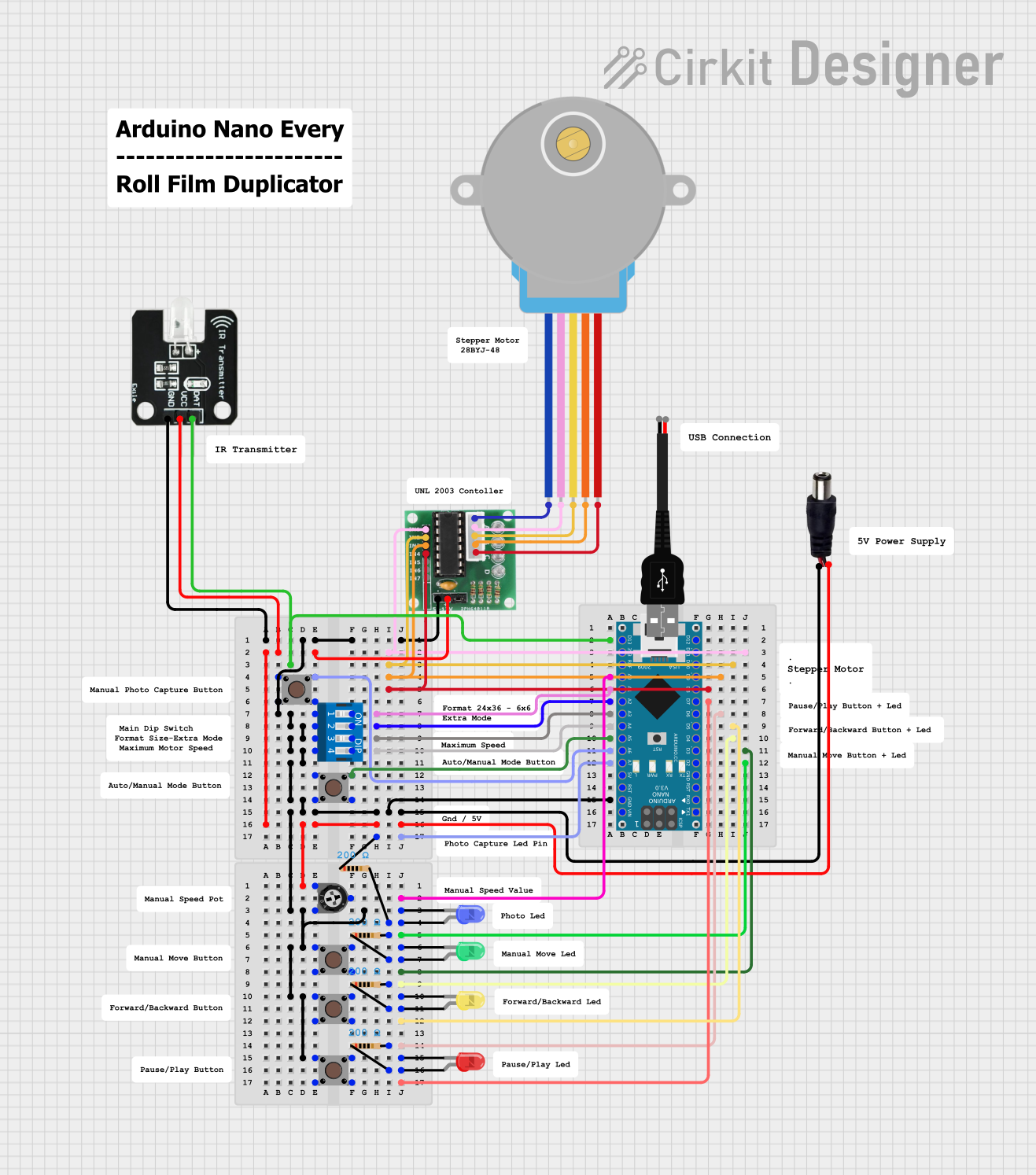
Explore Projects Built with ULN 2003
Common Applications and Use Cases
- Stepper motor driving for precise control in 3D printers and CNC machines
- Relay driving for home automation systems
- LED display and lighting control
- Driving various inductive loads like solenoids and relays
Technical Specifications
Key Technical Details
- Output Voltage (VOUT): 50V (max)
- Output Current (IOUT): 500mA per channel (max)
- Input Voltage (VIN): 5V (typical, from microcontroller)
- Clamping Voltage: 50V (max)
- Package: 16-pin DIP (Dual In-line Package)
Pin Configuration and Descriptions
| Pin Number | Name | Description |
|---|---|---|
| 1-7 | IN1-IN7 | Input pins for the seven Darlington pairs |
| 8 | GND | Ground pin |
| 9-15 | OUT1-OUT7 | Output pins for the seven Darlington pairs |
| 16 | COM | Common pin for clamp diodes |
Usage Instructions
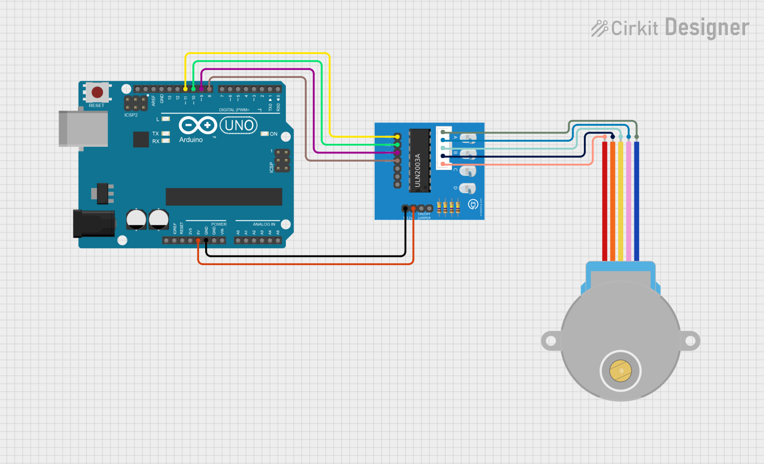
How to Use the Component in a Circuit
- Connect the input pins (IN1-IN7) to the digital outputs of a microcontroller.
- Connect the output pins (OUT1-OUT7) to the stepper motor coils.
- Connect the COM pin to the positive supply voltage if clamp diodes are required for inductive load protection.
- Connect the GND pin to the ground of the power supply and microcontroller.
Important Considerations and Best Practices
- Ensure that the power supply voltage does not exceed the maximum rating of 50V.
- Do not exceed the maximum current rating of 500mA per channel.
- Use appropriate base resistors if the microcontroller's output current is not sufficient to drive the input pins.
- Provide adequate heat sinking if the module is expected to operate near its maximum current rating.
Troubleshooting and FAQs
Common Issues Users Might Face
- Motor not turning: Check the connections and ensure that the input signals from the microcontroller are being received.
- Overheating: Ensure that the current through the Darlington pairs does not exceed 500mA per channel.
- Unexpected behavior: Verify that the power supply is stable and within the specified voltage range.
Solutions and Tips for Troubleshooting
- Double-check wiring, especially the ground and power connections.
- Use a multimeter to verify the input signals and output voltages.
- Ensure that the microcontroller's code is correctly generating the step sequence for the stepper motor.
FAQs
Q: Can I drive a bipolar stepper motor with the ULN2003? A: Yes, but you will need to use two channels per coil and ensure that the current requirements do not exceed the module's specifications.
Q: What is the purpose of the clamp diodes? A: The clamp diodes protect the driver from voltage spikes caused by the inductive loads when the current through them is suddenly switched off.
Q: Can I use the ULN2003 to drive loads other than stepper motors? A: Yes, the ULN2003 can drive a variety of inductive loads including relays, solenoids, and DC motors.
Example Code for Arduino UNO
// Define the ULN2003 control pins connected to the Arduino
const int motorPin1 = 2; // IN1 on the ULN2003
const int motorPin2 = 3; // IN2 on the ULN2003
const int motorPin3 = 4; // IN3 on the ULN2003
const int motorPin4 = 5; // IN4 on the ULN2003

void setup() {
  // Set the motor control pins as outputs
  pinMode(motorPin1, OUTPUT);
  pinMode(motorPin2, OUTPUT);
  pinMode(motorPin3, OUTPUT);
  pinMode(motorPin4, OUTPUT);
}

void loop() {
  // This function will step the motor one step
  stepMotor();
  delay(100); // Wait 100ms between each step
}

void stepMotor() {
  // This sequence is for a 4-step full rotation
  digitalWrite(motorPin1, HIGH);
  digitalWrite(motorPin2, LOW);
  digitalWrite(motorPin3, LOW);
  digitalWrite(motorPin4, LOW);
  delay(10);

  digitalWrite(motorPin1, LOW);
  digitalWrite(motorPin2, HIGH);
  digitalWrite(motorPin3, LOW);
  digitalWrite(motorPin4, LOW);
  delay(10);

  digitalWrite(motorPin1, LOW);
  digitalWrite(motorPin2, LOW);
  digitalWrite(motorPin3, HIGH);
  digitalWrite(motorPin4, LOW);
  delay(10);

  digitalWrite(motorPin1, LOW);
  digitalWrite(motorPin2, LOW);
  digitalWrite(motorPin3, LOW);
  digitalWrite(motorPin4, HIGH);
  delay(10);
}
This example demonstrates a simple 4-step sequence to rotate a stepper motor connected to an Arduino UNO using the ULN2003 driver module. The code comments are kept concise to adhere to the 80-character line length limit.