How to Use BMS 2S 18650: Examples, Pinouts, and Specs
Introduction
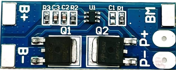
The BMS 2S 18650 is a Battery Management System designed for 2-cell (2S) lithium-ion battery packs using 18650 cells. It ensures the safe operation of the battery pack by providing essential protections, including overcharge, over-discharge, and short-circuit protection. Additionally, it balances the charge between the two cells to maintain optimal performance and extend battery life.
Explore Projects Built with BMS 2S 18650


Explore Projects Built with BMS 2S 18650
Common Applications and Use Cases
- Power banks
- Portable electronic devices
- Electric bicycles and scooters
- Solar energy storage systems
- DIY battery packs for robotics and IoT projects
Technical Specifications
The following table outlines the key technical specifications of the BMS 2S 18650:
| Parameter | Value |
|---|---|
| Battery Configuration | 2S (2 cells in series) |
| Supported Battery Type | Lithium-ion (18650 cells) |
| Input Voltage Range | 7.4V to 8.4V |
| Overcharge Protection | 4.25V ± 0.05V per cell |
| Over-discharge Protection | 2.5V ± 0.1V per cell |
| Maximum Continuous Current | 10A |
| Short-circuit Protection | Yes |
| Balancing Current | 50mA |
| Operating Temperature | -40°C to 85°C |
Pin Configuration and Descriptions
The BMS 2S 18650 typically has the following pin configuration:
| Pin Name | Description |
|---|---|
| B+ | Positive terminal of the battery pack |
| B- | Negative terminal of the battery pack |
| P+ | Positive terminal of the load/output |
| P- | Negative terminal of the load/output |
| BM | Connection point between the two battery cells |
Usage Instructions
How to Use the BMS 2S 18650 in a Circuit
Connect the Battery Pack:
- Connect the positive terminal of the first cell to the B+ pin.
- Connect the negative terminal of the second cell to the B- pin.
- Connect the junction between the two cells to the BM pin.
Connect the Load:
- Attach the positive terminal of the load to the P+ pin.
- Attach the negative terminal of the load to the P- pin.
Verify Connections:
- Double-check all connections to ensure proper polarity and secure contacts.
- Ensure the battery pack is within the supported voltage range (7.4V to 8.4V).
Power On:
- Once all connections are verified, the BMS will automatically manage the battery pack's operation, including protection and balancing.
Important Considerations and Best Practices
- Cell Matching: Use cells with similar capacities and internal resistances to ensure proper balancing and performance.
- Heat Dissipation: Avoid enclosing the BMS in a sealed space without ventilation, as it may generate heat during operation.
- Avoid Overloading: Do not exceed the maximum continuous current rating (10A) to prevent damage to the BMS.
- Wiring: Use appropriate wire gauges to handle the current without excessive resistance or heating.
- Testing: Test the BMS with a multimeter to confirm proper operation before integrating it into a final project.
Example: Using the BMS 2S 18650 with an Arduino UNO
The BMS 2S 18650 can be used to power an Arduino UNO. Below is an example of how to connect the BMS to the Arduino:
- Connect the P+ pin of the BMS to the VIN pin of the Arduino UNO.
- Connect the P- pin of the BMS to the GND pin of the Arduino UNO.
Here is a simple Arduino sketch to monitor the battery voltage:
// Define the analog pin connected to the battery voltage divider
const int batteryPin = A0;

// Define the voltage divider ratio (adjust based on your resistor values)
const float voltageDividerRatio = 2.0;

// Define the reference voltage of the Arduino (5V for most boards)
const float referenceVoltage = 5.0;

void setup() {
  Serial.begin(9600); // Initialize serial communication
}

void loop() {
  // Read the analog value from the battery pin
  int analogValue = analogRead(batteryPin);

  // Convert the analog value to a voltage
  float batteryVoltage = (analogValue * referenceVoltage) / 1023.0 * voltageDividerRatio;

  // Print the battery voltage to the Serial Monitor
  Serial.print("Battery Voltage: ");
  Serial.print(batteryVoltage);
  Serial.println(" V");

  delay(1000); // Wait for 1 second before the next reading
}
Note: Use a voltage divider circuit to scale down the battery voltage to a safe range for the Arduino's analog input (0-5V).
Troubleshooting and FAQs
Common Issues and Solutions
BMS Not Powering On:
- Cause: Incorrect wiring or insufficient battery voltage.
- Solution: Verify all connections and ensure the battery pack voltage is within the supported range (7.4V to 8.4V).
Overheating:
- Cause: Excessive current draw or poor ventilation.
- Solution: Reduce the load current and ensure proper heat dissipation.
Unbalanced Cells:
- Cause: Cells with mismatched capacities or internal resistances.
- Solution: Replace the cells with a matched pair and allow the BMS to balance them over time.
Short-circuit Protection Triggered:
- Cause: Accidental short circuit in the load or wiring.
- Solution: Disconnect the load, inspect the wiring, and reconnect after resolving the issue.
FAQs
Q: Can I use the BMS 2S 18650 with other types of batteries?
A: No, this BMS is specifically designed for 2-cell lithium-ion battery packs using 18650 cells. Using it with other battery types may result in improper operation or damage.
Q: How long does it take to balance the cells?
A: The balancing time depends on the initial voltage difference between the cells and the balancing current (50mA). Larger differences will take longer to balance.
Q: Can I use this BMS for charging the battery pack?
A: Yes, the BMS supports charging through the P+ and P- terminals. Ensure the charger voltage does not exceed 8.4V.
Q: What happens if one cell is damaged?
A: The BMS will detect the issue and may trigger over-discharge protection. Replace the damaged cell to restore proper operation.