How to Use driver : Examples, Pinouts, and Specs
Introduction
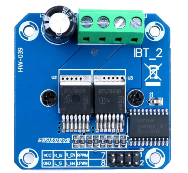
A driver is an electronic component designed to provide the necessary current and voltage to control other components, such as motors, LEDs, or other high-power devices. Drivers act as intermediaries between control circuits (e.g., microcontrollers) and the load, ensuring proper operation and performance by amplifying signals or providing sufficient power.
Explore Projects Built with driver
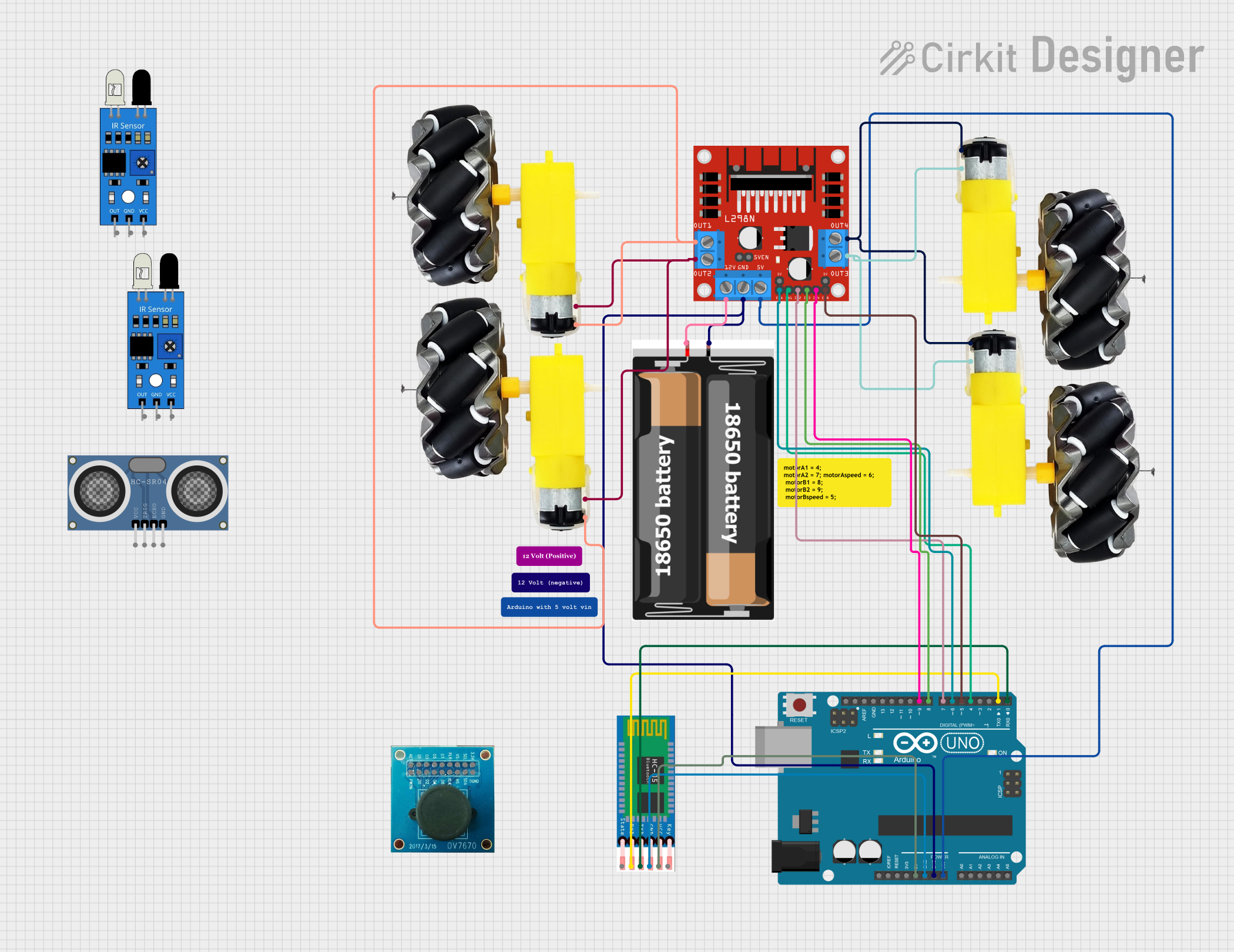
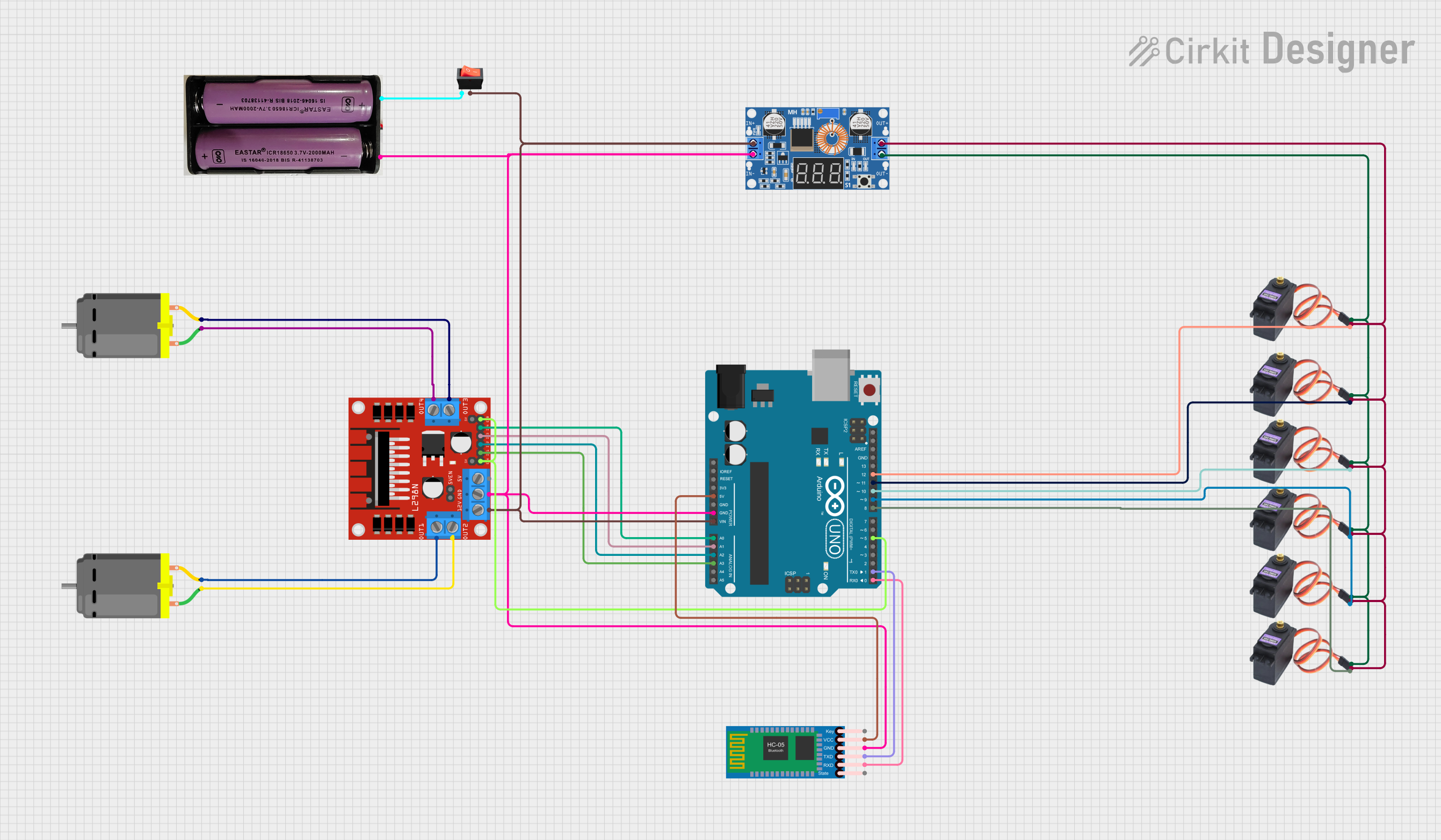
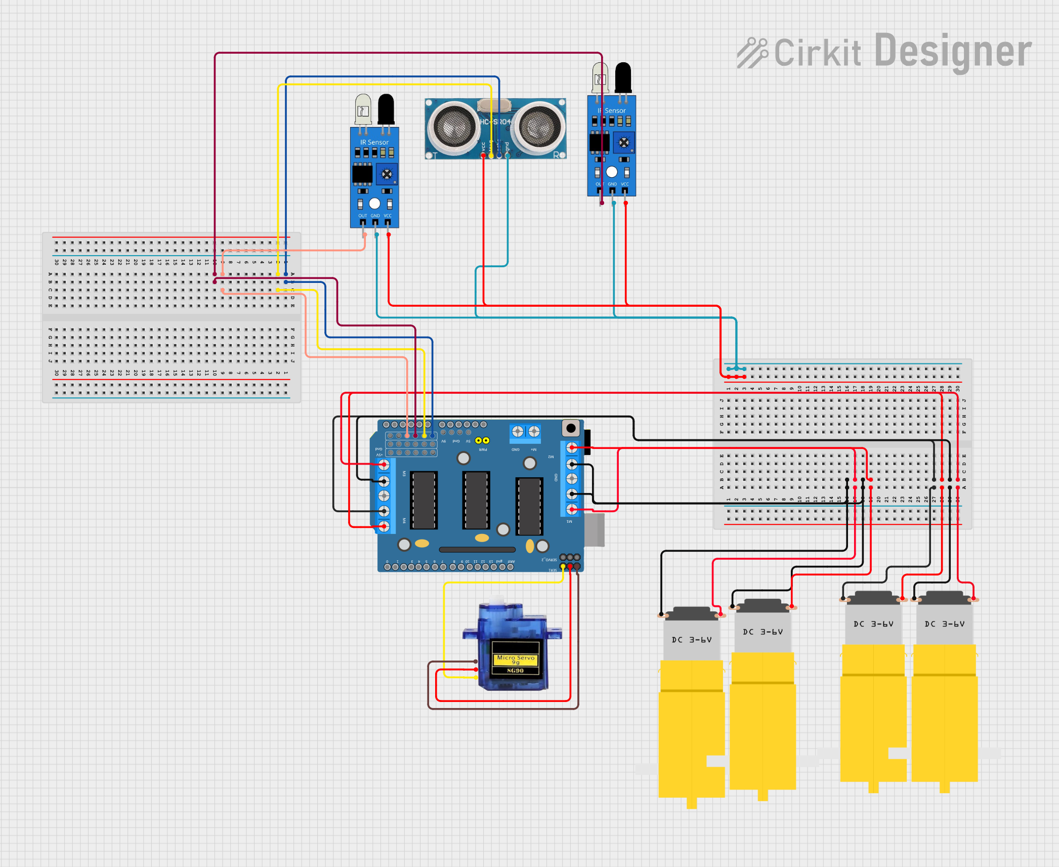
Explore Projects Built with driver
Common Applications and Use Cases
- Driving DC motors, stepper motors, or servo motors in robotics and automation.
- Controlling high-power LEDs in lighting systems.
- Powering solenoids, relays, or other electromechanical devices.
- Interfacing low-power microcontrollers with high-power loads.
Technical Specifications
The technical specifications of a driver vary depending on its type and intended application. Below is a general overview of key parameters:
| Parameter | Description |
|---|---|
| Input Voltage Range | Voltage range required to operate the driver (e.g., 3.3V, 5V, or 12V). |
| Output Voltage Range | Voltage supplied to the load (e.g., 5V, 12V, or higher, depending on the driver). |
| Output Current | Maximum current the driver can supply to the load (e.g., 1A, 2A, or more). |
| Control Signal Voltage | Voltage level required for control signals (e.g., 3.3V or 5V logic). |
| Efficiency | Percentage of input power effectively delivered to the load. |
| Protection Features | Overcurrent, overvoltage, thermal shutdown, or reverse polarity protection. |
Pin Configuration and Descriptions
Below is an example of a typical motor driver IC pinout (e.g., L298N Dual H-Bridge Motor Driver):
| Pin Name | Pin Number | Description |
|---|---|---|
| IN1 | 1 | Input control signal for Motor A (logic HIGH or LOW). |
| IN2 | 2 | Input control signal for Motor A (logic HIGH or LOW). |
| ENA | 3 | Enable pin for Motor A (PWM signal for speed control). |
| OUT1 | 4 | Output terminal for Motor A. |
| OUT2 | 5 | Output terminal for Motor A. |
| VCC | 6 | Power supply for the driver (e.g., 5V or 12V). |
| GND | 7 | Ground connection. |
| IN3 | 8 | Input control signal for Motor B (logic HIGH or LOW). |
| IN4 | 9 | Input control signal for Motor B (logic HIGH or LOW). |
| ENB | 10 | Enable pin for Motor B (PWM signal for speed control). |
| OUT3 | 11 | Output terminal for Motor B. |
| OUT4 | 12 | Output terminal for Motor B. |
Usage Instructions
How to Use the Component in a Circuit
- Power the Driver: Connect the VCC pin to the appropriate power supply and the GND pin to ground.
- Connect the Load: Attach the load (e.g., motor or LED) to the output pins (e.g., OUT1 and OUT2 for Motor A).
- Control Signals: Use a microcontroller or other control circuit to send logic signals to the input pins (e.g., IN1 and IN2) to control the load.
- Enable the Driver: If the driver has enable pins (e.g., ENA and ENB), provide a PWM signal or logic HIGH to activate the corresponding outputs.
Important Considerations and Best Practices
- Match Voltage and Current Ratings: Ensure the driver's output voltage and current ratings match the requirements of the load.
- Use Heat Sinks if Necessary: For high-power applications, consider adding a heat sink to prevent overheating.
- Decoupling Capacitors: Place decoupling capacitors near the power supply pins to reduce noise and voltage fluctuations.
- Avoid Overloading: Do not exceed the driver's maximum current rating to prevent damage.
- Check Logic Levels: Ensure the control signals are compatible with the driver's input voltage levels.
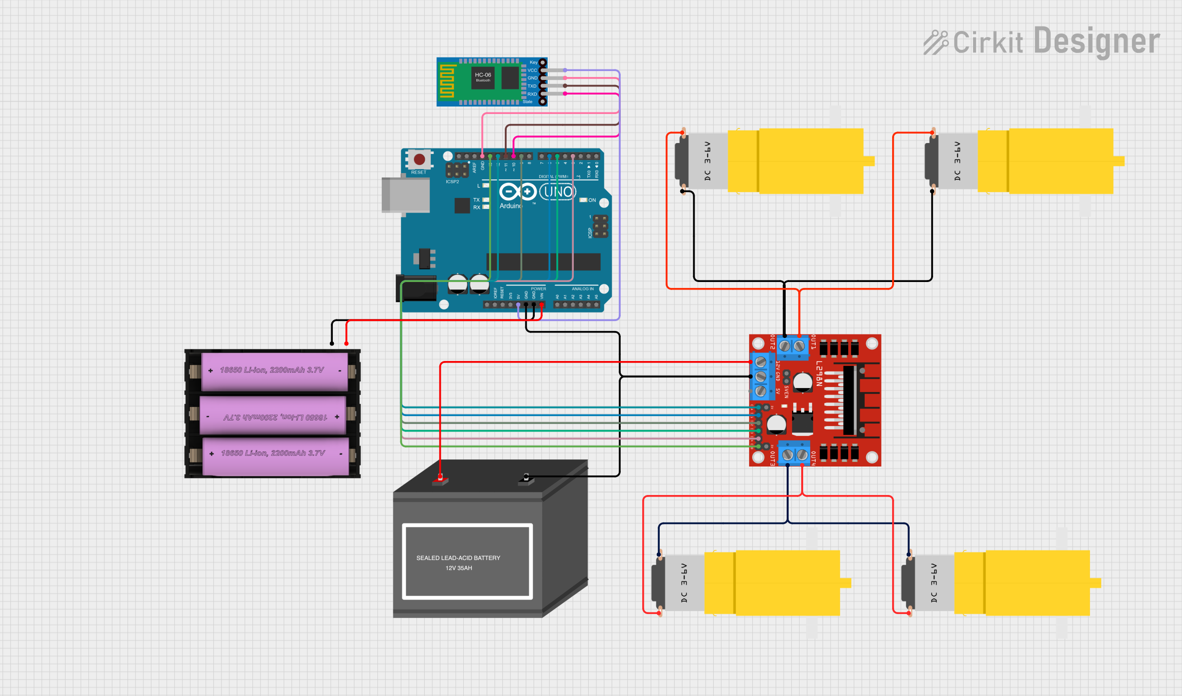
Example: Controlling a DC Motor with Arduino UNO
Below is an example of how to use an L298N motor driver to control a DC motor with an Arduino UNO:
// Define motor control pins
const int IN1 = 9;  // Input pin 1 for Motor A
const int IN2 = 8;  // Input pin 2 for Motor A
const int ENA = 10; // Enable pin for Motor A (PWM)

// Setup function to initialize pins
void setup() {
  pinMode(IN1, OUTPUT); // Set IN1 as output
  pinMode(IN2, OUTPUT); // Set IN2 as output
  pinMode(ENA, OUTPUT); // Set ENA as output
}

// Loop function to control motor
void loop() {
  // Rotate motor forward
  digitalWrite(IN1, HIGH); // Set IN1 HIGH
  digitalWrite(IN2, LOW);  // Set IN2 LOW
  analogWrite(ENA, 128);   // Set speed to 50% (PWM value: 128 out of 255)
  delay(2000);             // Run for 2 seconds

  // Stop motor
  digitalWrite(IN1, LOW);  // Set IN1 LOW
  digitalWrite(IN2, LOW);  // Set IN2 LOW
  delay(1000);             // Wait for 1 second

  // Rotate motor backward
  digitalWrite(IN1, LOW);  // Set IN1 LOW
  digitalWrite(IN2, HIGH); // Set IN2 HIGH
  analogWrite(ENA, 128);   // Set speed to 50% (PWM value: 128 out of 255)
  delay(2000);             // Run for 2 seconds

  // Stop motor
  digitalWrite(IN1, LOW);  // Set IN1 LOW
  digitalWrite(IN2, LOW);  // Set IN2 LOW
  delay(1000);             // Wait for 1 second
}
Troubleshooting and FAQs
Common Issues and Solutions
Motor Does Not Turn On
- Cause: Insufficient power supply or incorrect wiring.
- Solution: Verify the power supply voltage and current. Check all connections.
Driver Overheats
- Cause: Excessive current draw or inadequate cooling.
- Solution: Ensure the load does not exceed the driver's current rating. Add a heat sink or cooling fan.
Erratic Motor Behavior
- Cause: Noise or unstable control signals.
- Solution: Use decoupling capacitors near the power supply pins. Ensure control signals are stable.
No Response to Control Signals
- Cause: Incorrect logic levels or damaged driver.
- Solution: Verify the control signal voltage levels. Replace the driver if necessary.
FAQs
Can I use a driver with a 3.3V microcontroller?
- Yes, but ensure the driver's input pins are compatible with 3.3V logic levels.
What happens if I exceed the driver's current rating?
- Exceeding the current rating can damage the driver or cause it to shut down due to thermal protection.
Do I need a separate power supply for the load?
- It depends on the driver's design. Some drivers require a separate power supply for the load, while others can share the same supply.
By following this documentation, you can effectively use a driver in your electronic projects while avoiding common pitfalls.