How to Use pump 12vdc: Examples, Pinouts, and Specs
Introduction
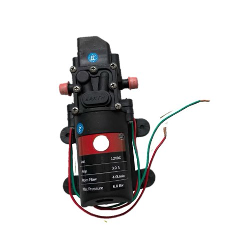
A 12V DC pump is an electromechanical device designed to move fluids by converting electrical energy into mechanical energy. It operates on a 12-volt direct current (DC) power supply, making it suitable for a wide range of low-voltage applications. These pumps are compact, efficient, and versatile, making them ideal for use in aquariums, automotive systems (e.g., windshield washers or coolant circulation), small-scale irrigation systems, and water transfer tasks in DIY projects.
Explore Projects Built with pump 12vdc

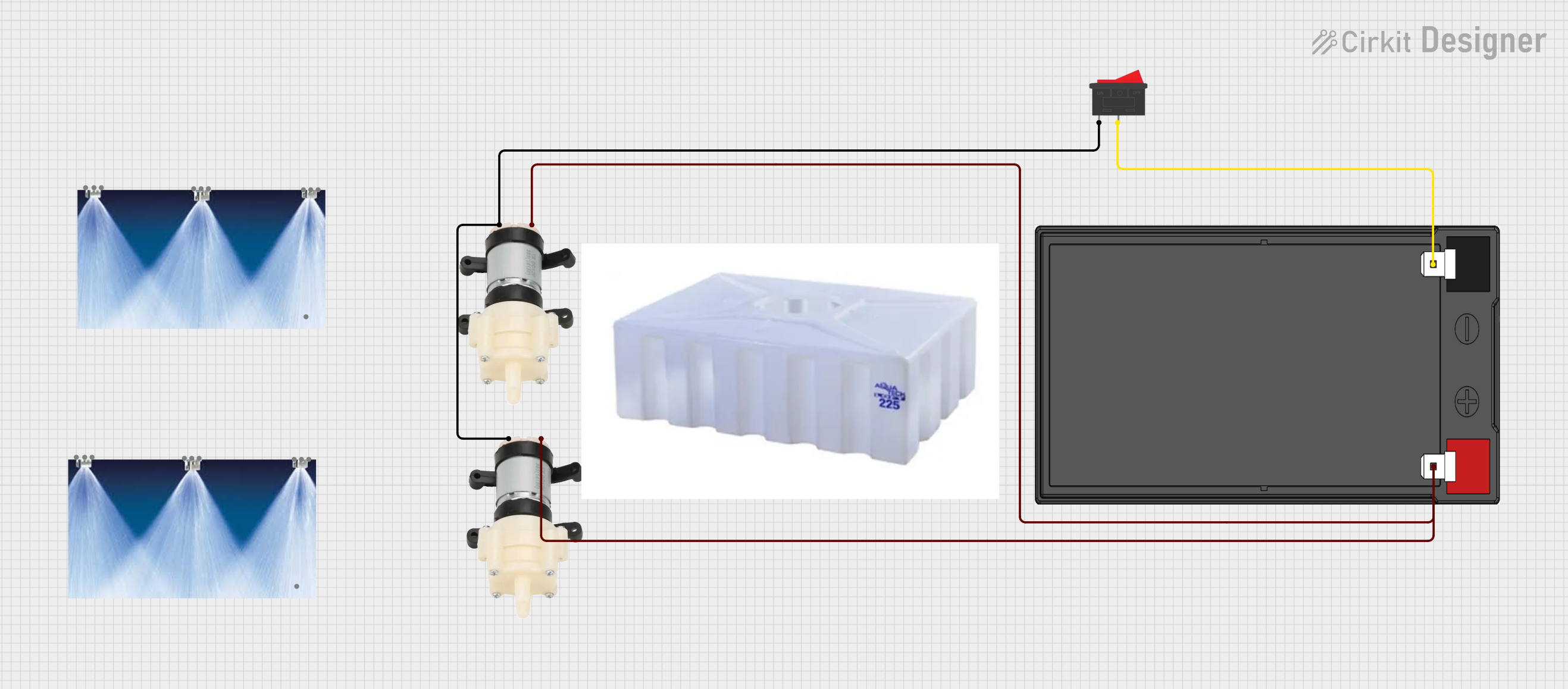
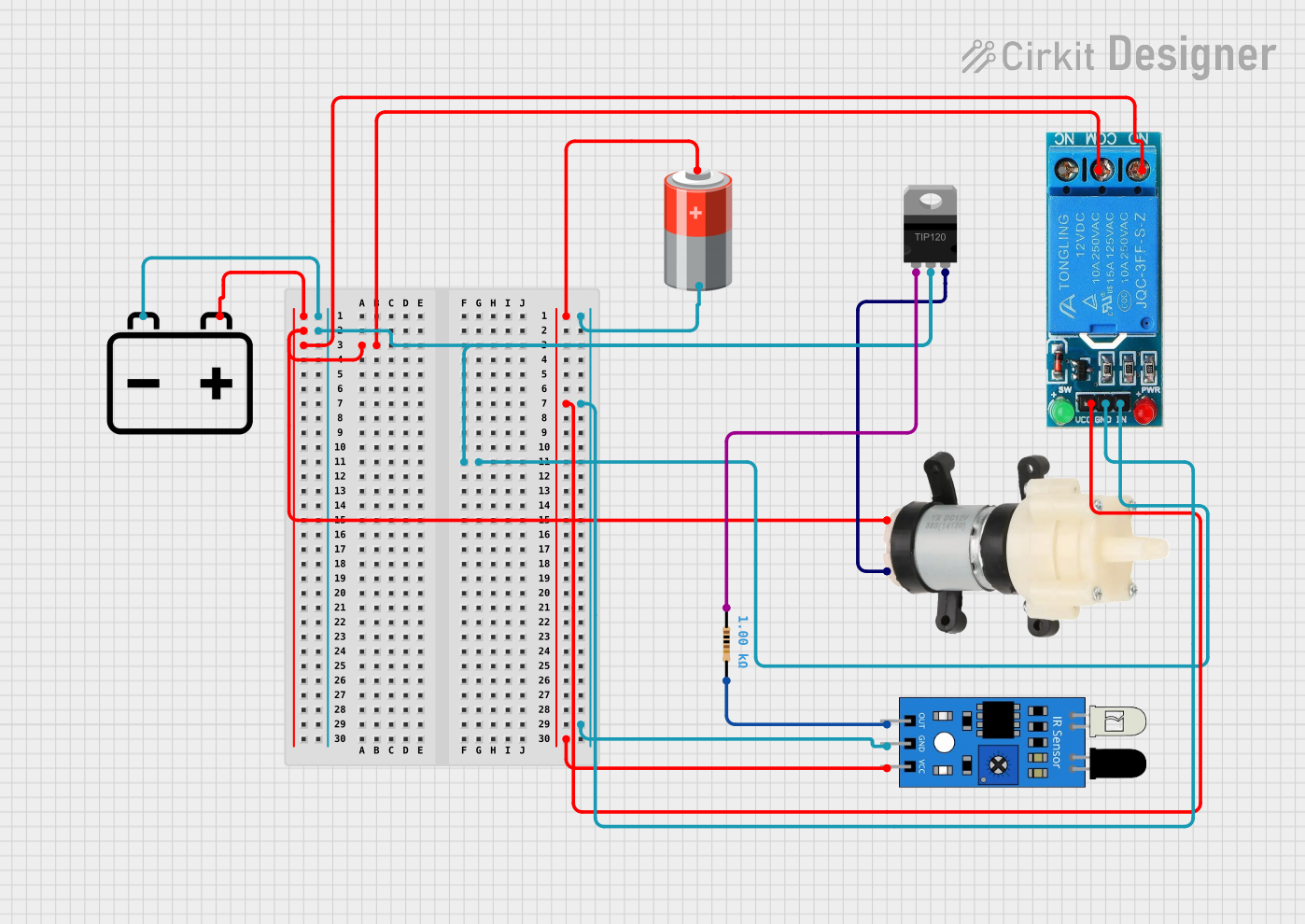
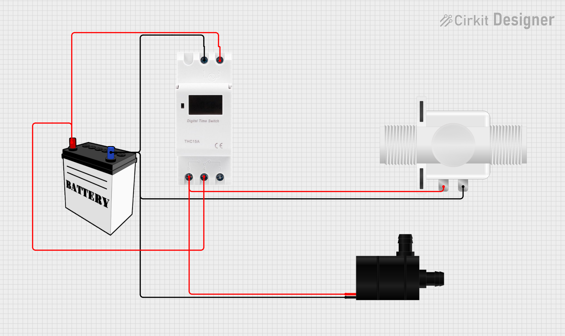
Explore Projects Built with pump 12vdc
Technical Specifications
Below are the key technical details of a typical 12V DC pump:
| Parameter | Value |
|---|---|
| Operating Voltage | 12V DC |
| Operating Current | 0.5A to 2A (varies by model) |
| Power Consumption | 6W to 24W |
| Maximum Flow Rate | 1 to 5 liters per minute (L/min) |
| Maximum Lift Height | 1 to 5 meters (varies by model) |
| Inlet/Outlet Diameter | 6mm to 12mm (varies by model) |
| Material | Plastic or metal housing |
| Operating Temperature | 0°C to 60°C |
| Noise Level | < 50 dB |
Pin Configuration and Descriptions
The 12V DC pump typically has two wires for electrical connection:
| Wire Color | Function | Description |
|---|---|---|
| Red | Positive (+) Terminal | Connect to the positive terminal of the 12V DC power supply. |
| Black | Negative (-) Terminal | Connect to the ground or negative terminal of the power supply. |
Usage Instructions
How to Use the 12V DC Pump in a Circuit
- Power Supply: Ensure you have a stable 12V DC power source capable of supplying sufficient current (check the pump's current rating).
- Polarity: Connect the red wire to the positive terminal of the power supply and the black wire to the negative terminal.
- Fluid Connections: Attach hoses to the inlet and outlet ports of the pump. Ensure the connections are secure to prevent leaks.
- Priming: If required, prime the pump by filling it with fluid before powering it on to avoid dry running.
- Control: Optionally, you can control the pump using a relay module or a transistor circuit connected to a microcontroller like an Arduino.
Important Considerations and Best Practices
- Avoid Dry Running: Running the pump without fluid can damage the internal components.
- Voltage Regulation: Use a regulated 12V DC power supply to prevent overvoltage, which can damage the pump.
- Filtration: Use a filter on the inlet side to prevent debris from entering and clogging the pump.
- Mounting: Securely mount the pump to minimize vibrations and noise during operation.
- Temperature Limits: Do not operate the pump outside its specified temperature range to avoid overheating or damage.
Example: Controlling a 12V DC Pump with an Arduino UNO
Below is an example of how to control a 12V DC pump using an Arduino UNO and a relay module:
/*
  Example: Controlling a 12V DC Pump with Arduino UNO
  This code turns the pump ON for 5 seconds and OFF for 5 seconds in a loop.
  Ensure the relay module is connected properly to the Arduino and pump.
*/

const int relayPin = 7; // Pin connected to the relay module

void setup() {
  pinMode(relayPin, OUTPUT); // Set the relay pin as an output
  digitalWrite(relayPin, LOW); // Ensure the relay is initially OFF
}

void loop() {
  digitalWrite(relayPin, HIGH); // Turn the pump ON
  delay(5000); // Keep the pump ON for 5 seconds
  digitalWrite(relayPin, LOW); // Turn the pump OFF
  delay(5000); // Keep the pump OFF for 5 seconds
}
Wiring Notes:
- Connect the relay module's control pin to Arduino pin 7.
- Connect the pump's positive wire to the relay's normally open (NO) terminal.
- Connect the pump's negative wire to the power supply ground.
- Connect the relay's common (COM) terminal to the 12V DC power supply positive terminal.
Troubleshooting and FAQs
Common Issues and Solutions
Pump Does Not Start:
- Cause: Insufficient power supply or incorrect wiring.
- Solution: Verify the power supply voltage and current ratings. Check the wiring for proper polarity.
Low Flow Rate:
- Cause: Clogged inlet or outlet, or insufficient power.
- Solution: Clean the inlet and outlet ports. Ensure the power supply meets the pump's requirements.
Excessive Noise:
- Cause: Loose mounting or air trapped in the pump.
- Solution: Securely mount the pump and ensure it is properly primed.
Pump Overheats:
- Cause: Operating outside the temperature range or running dry.
- Solution: Operate within the specified temperature range and avoid dry running.
FAQs
Can I use a 12V DC pump with a battery?
- Yes, you can use a 12V battery as long as it provides sufficient current for the pump.
Is the pump waterproof?
- Most 12V DC pumps are water-resistant but not fully waterproof. Check the manufacturer's specifications for details.
Can I control the pump speed?
- Yes, you can control the speed using a PWM (Pulse Width Modulation) controller or a motor driver circuit.
What type of fluids can the pump handle?
- The pump is typically designed for water or other non-corrosive liquids. Avoid using it with corrosive or highly viscous fluids unless specified by the manufacturer.