How to Use OV7076: Examples, Pinouts, and Specs
Introduction
The OV7076 is a high-performance image sensor specifically designed for automotive applications. It features advanced image processing capabilities, excellent low-light performance, and robust reliability, making it ideal for use in driver assistance systems, parking cameras, and other automotive imaging solutions. Its compact design and high sensitivity allow it to deliver clear and detailed images even in challenging lighting conditions.
Explore Projects Built with OV7076


Explore Projects Built with OV7076
Common Applications
- Driver assistance systems (ADAS)
- Rear-view and surround-view cameras
- Parking assistance systems
- Lane departure warning systems
- Traffic sign recognition
Technical Specifications
Key Technical Details
| Parameter | Value |
|---|---|
| Sensor Type | CMOS Image Sensor |
| Resolution | VGA (640 x 480 pixels) |
| Pixel Size | 6.0 µm x 6.0 µm |
| Optical Format | 1/4 inch |
| Frame Rate | Up to 60 frames per second (fps) |
| Dynamic Range | 72 dB |
| Supply Voltage | 3.3V (Analog), 1.8V (Digital) |
| Operating Temperature Range | -40°C to +85°C |
| Interface | Parallel (DVP) |
| Shutter Type | Rolling Shutter |
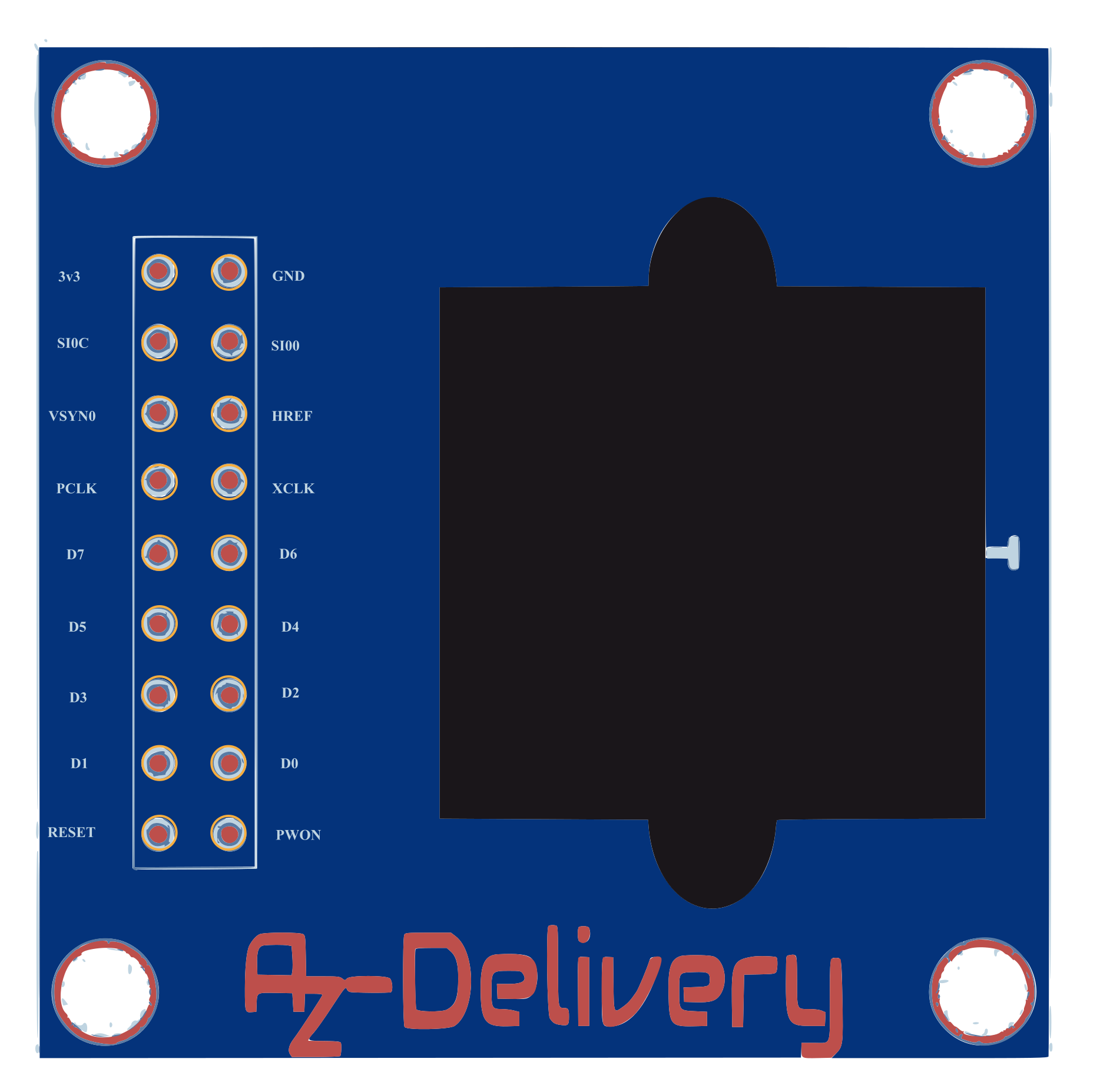
Pin Configuration and Descriptions
| Pin Number | Pin Name | Description |
|---|---|---|
| 1 | VDD | 3.3V Analog Power Supply |
| 2 | GND | Ground |
| 3 | D0-D7 | Parallel Data Output (8-bit) |
| 4 | PCLK | Pixel Clock Output |
| 5 | HREF | Horizontal Reference Signal |
| 6 | VSYNC | Vertical Synchronization Signal |
| 7 | RESET | Active Low Reset Input |
| 8 | SCL | I2C Clock Line |
| 9 | SDA | I2C Data Line |
| 10 | XCLK | External Clock Input |
Usage Instructions
How to Use the OV7076 in a Circuit
- Power Supply: Connect the OV7076 to a 3.3V analog power supply and a 1.8V digital power supply. Ensure proper decoupling capacitors are used to minimize noise.
- Clock Input: Provide an external clock signal (XCLK) to the sensor. A typical frequency is 24 MHz.
- I2C Communication: Use the I2C interface (SCL and SDA pins) to configure the sensor's registers. This allows you to adjust settings such as exposure, gain, and image format.
- Data Output: The image data is output through the parallel data pins (D0-D7) synchronized with the pixel clock (PCLK). Use the HREF and VSYNC signals to determine the start and end of each frame and line.
- Reset: Use the RESET pin to initialize the sensor during power-up or to recover from errors.
Important Considerations and Best Practices
- Decoupling Capacitors: Place decoupling capacitors close to the power supply pins to reduce noise and ensure stable operation.
- Clock Stability: Ensure the external clock signal (XCLK) is stable and free of jitter to avoid image artifacts.
- Thermal Management: Operate the sensor within its specified temperature range (-40°C to +85°C) to prevent damage and ensure optimal performance.
- Lens Selection: Use a lens compatible with the sensor's 1/4-inch optical format for optimal image quality.
- I2C Pull-Up Resistors: Add pull-up resistors (typically 4.7 kΩ) to the I2C lines (SCL and SDA) for proper communication.
Example: Connecting OV7076 to an Arduino UNO
Below is an example of how to interface the OV7076 with an Arduino UNO for basic image capture:
#include <Wire.h> // Include the I2C library for communication

#define OV7076_I2C_ADDRESS 0x42 // OV7076 default I2C address

void setup() {
  Wire.begin(); // Initialize I2C communication
  Serial.begin(9600); // Initialize serial communication for debugging

  // Reset the OV7076 sensor
  pinMode(7, OUTPUT); // Assuming RESET pin is connected to Arduino pin 7
  digitalWrite(7, LOW); // Hold RESET low
  delay(10); // Wait for 10ms
  digitalWrite(7, HIGH); // Release RESET
  delay(100); // Wait for the sensor to initialize

  // Configure the OV7076 sensor
  configureOV7076();
}

void loop() {
  // Main loop can be used to process image data
}

void configureOV7076() {
  // Example: Write to a register (replace 0x12 and 0x80 with actual register
  // address and value based on the OV7076 datasheet)
  Wire.beginTransmission(OV7076_I2C_ADDRESS);
  Wire.write(0x12); // Register address
  Wire.write(0x80); // Register value
  Wire.endTransmission();

  Serial.println("OV7076 configured successfully!");
}
Notes:
- Replace the register address and value in the
configureOV7076function with actual values from the OV7076 datasheet. - The Arduino UNO may not have sufficient processing power or memory for advanced image processing. Use a more powerful microcontroller or development board for complex applications.
Troubleshooting and FAQs
Common Issues and Solutions
No Image Output:
- Cause: Incorrect power supply or clock signal.
- Solution: Verify the power supply voltages (3.3V and 1.8V) and ensure the XCLK signal is stable.
I2C Communication Fails:
- Cause: Missing pull-up resistors on the I2C lines.
- Solution: Add 4.7 kΩ pull-up resistors to the SCL and SDA lines.
Image Artifacts or Noise:
- Cause: Insufficient decoupling or unstable clock signal.
- Solution: Add decoupling capacitors near the power pins and ensure the clock source is stable.
Sensor Overheating:
- Cause: Operating outside the specified temperature range.
- Solution: Ensure proper ventilation and avoid exposure to extreme temperatures.
FAQs
Q: Can the OV7076 be used in non-automotive applications?
A: Yes, the OV7076 can be used in any application requiring a high-performance image sensor, such as robotics or security cameras.Q: What is the maximum frame rate of the OV7076?
A: The OV7076 supports up to 60 frames per second (fps) at VGA resolution.Q: Does the OV7076 support night vision?
A: The OV7076 has excellent low-light performance, making it suitable for night-time applications when paired with an appropriate infrared (IR) light source.Q: Can the OV7076 output color images?
A: Yes, the OV7076 supports color image output when configured correctly.
This documentation provides a comprehensive guide to using the OV7076 image sensor effectively in your projects.