How to Use joystick: Examples, Pinouts, and Specs
Introduction
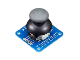
A joystick is an input device used to control video games or computer graphics. It consists of a stick that pivots on a base and reports its angle or direction to the device it is controlling. Joysticks are widely used in gaming, robotics, and other applications requiring precise directional control. They typically provide two-axis analog outputs (X and Y) and may include additional features such as push-button functionality.
Explore Projects Built with joystick


Explore Projects Built with joystick
Common Applications and Use Cases
- Gaming controllers for PCs and consoles
- Robotic arm or vehicle control
- Camera gimbal control
- Industrial machinery interfaces
- DIY electronics and Arduino projects
Technical Specifications
Below are the general technical specifications for a standard analog joystick module:
| Parameter | Value |
|---|---|
| Operating Voltage | 3.3V - 5V |
| Output Type | Analog (X and Y axes), Digital (SW) |
| X-Axis Range | 0V to Vcc |
| Y-Axis Range | 0V to Vcc |
| Button (SW) Output | Digital (Active Low) |
| Dimensions | ~34mm x 34mm x 32mm |
Pin Configuration and Descriptions
The joystick module typically has 5 pins. Below is the pinout description:
| Pin | Name | Description |
|---|---|---|
| 1 | GND | Ground connection |
| 2 | +VCC | Power supply (3.3V or 5V) |
| 3 | VRx | Analog output for the X-axis (horizontal movement) |
| 4 | VRy | Analog output for the Y-axis (vertical movement) |
| 5 | SW | Digital output for the push-button (active low when pressed, high when released) |
Usage Instructions
How to Use the Joystick in a Circuit
- Power the Joystick: Connect the
+VCCpin to a 3.3V or 5V power source and theGNDpin to ground. - Read Analog Outputs: Connect the
VRxandVRypins to the analog input pins of a microcontroller (e.g., Arduino) to read the X and Y axis values. - Read Button State: Connect the
SWpin to a digital input pin of the microcontroller to detect button presses.
Important Considerations and Best Practices
- Ensure the joystick is powered within its operating voltage range (3.3V to 5V).
- Use pull-up resistors if the
SWpin is not functioning as expected. - Avoid applying excessive force to the joystick to prevent mechanical damage.
- Calibrate the joystick in your software to account for variations in analog output values.
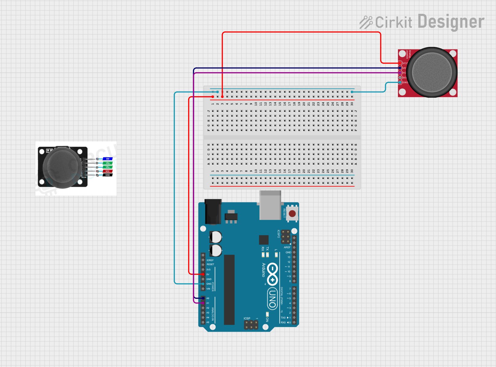
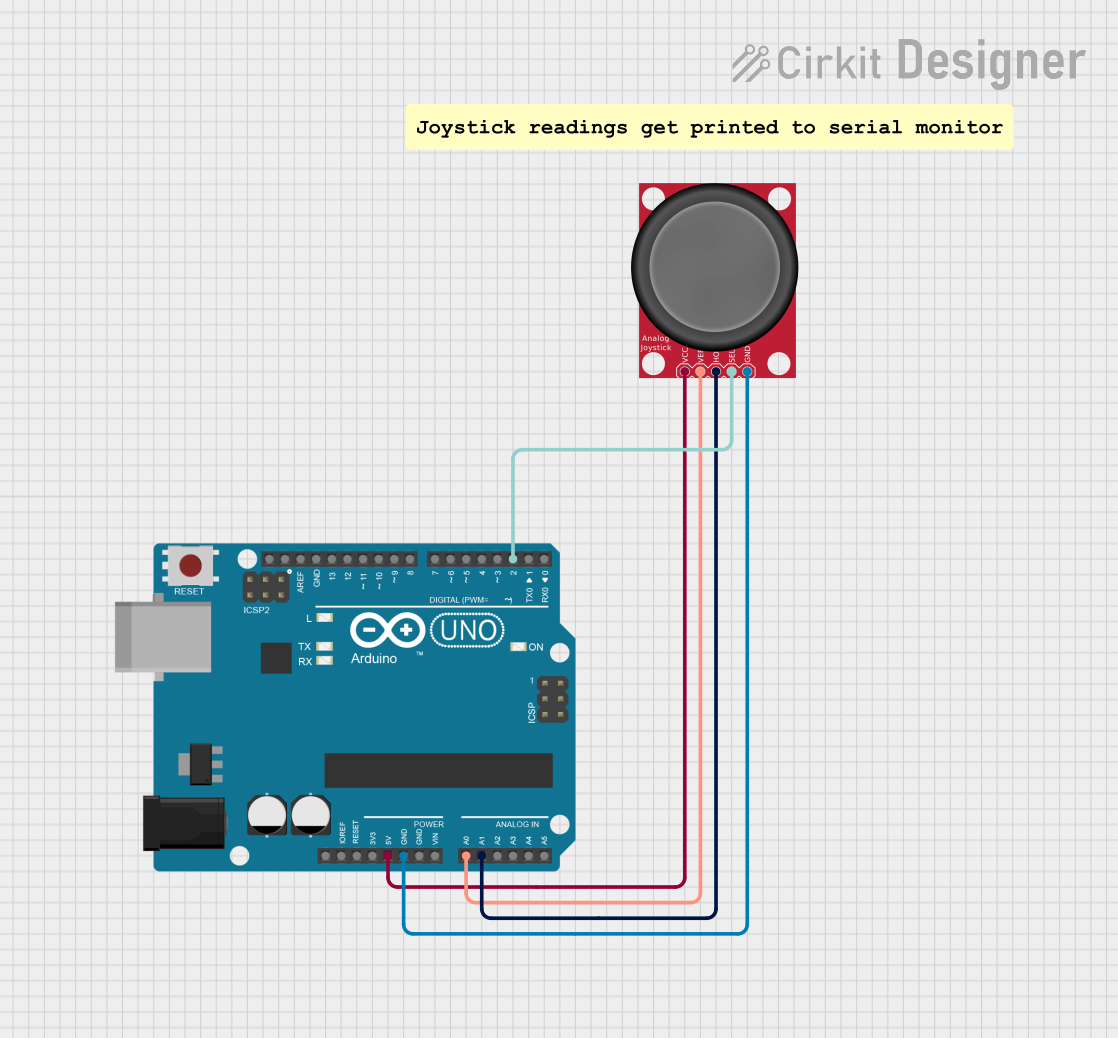
Example: Connecting the Joystick to an Arduino UNO
Below is an example of how to connect and use the joystick with an Arduino UNO:
Circuit Connections
+VCC→ 5V on ArduinoGND→ GND on ArduinoVRx→ A0 (Analog Pin 0)VRy→ A1 (Analog Pin 1)SW→ D2 (Digital Pin 2)
Arduino Code Example
// Define pin connections
const int VRx = A0; // X-axis analog pin
const int VRy = A1; // Y-axis analog pin
const int SW = 2;   // Push-button digital pin

void setup() {
  // Initialize serial communication for debugging
  Serial.begin(9600);

  // Configure the SW pin as input with an internal pull-up resistor
  pinMode(SW, INPUT_PULLUP);
}

void loop() {
  // Read the X and Y axis values (0 to 1023)
  int xValue = analogRead(VRx);
  int yValue = analogRead(VRy);

  // Read the button state (LOW when pressed, HIGH when released)
  int buttonState = digitalRead(SW);

  // Print the values to the Serial Monitor
  Serial.print("X: ");
  Serial.print(xValue);
  Serial.print(" | Y: ");
  Serial.print(yValue);
  Serial.print(" | Button: ");
  Serial.println(buttonState == LOW ? "Pressed" : "Released");

  // Add a small delay for stability
  delay(100);
}
Troubleshooting and FAQs
Common Issues and Solutions
Joystick Outputs Incorrect Values
- Cause: Loose or incorrect wiring.
- Solution: Double-check all connections and ensure the joystick is powered correctly.
Button (SW) Does Not Respond
- Cause: Missing pull-up resistor or incorrect pin configuration.
- Solution: Use the
INPUT_PULLUPmode in your microcontroller code for the SW pin.
Analog Values Are Unstable
- Cause: Electrical noise or poor power supply.
- Solution: Add decoupling capacitors (e.g., 0.1µF) near the power pins to reduce noise.
Joystick Does Not Return to Center
- Cause: Mechanical wear or damage.
- Solution: Replace the joystick module if it is physically damaged.
FAQs
Q: Can I use the joystick with a 3.3V microcontroller like ESP32?
A: Yes, the joystick works with 3.3V systems. Ensure the +VCC pin is connected to a 3.3V power source.
Q: How do I calibrate the joystick?
A: Read the analog values when the joystick is at rest. Use these values as the center point in your software to adjust for any offset.
Q: Can I use the joystick for digital-only applications?
A: Yes, you can use the SW pin for button functionality and ignore the analog outputs if not needed.