Cirkit Designer Logo
Cirkit Designer
Your all-in-one circuit design IDE
Home / 
Component Documentation

How to Use T-SIM7000G: Examples, Pinouts, and Specs

Image of T-SIM7000G
Cirkit Designer LogoDesign with T-SIM7000G in Cirkit Designer

Introduction

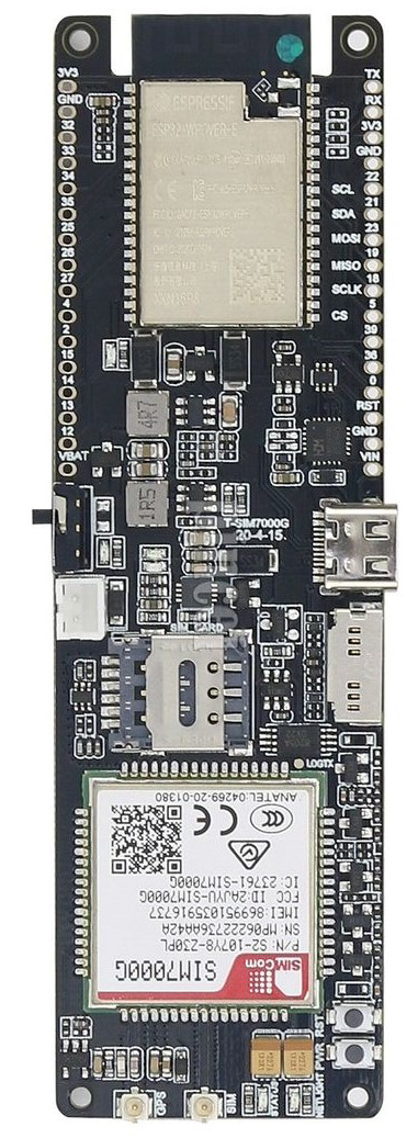
The T-SIM7000G is a versatile GSM/GPRS module manufactured by ESP32, designed for IoT applications. It supports multiple communication protocols, including LTE, and features low power consumption, making it ideal for battery-powered devices. Additionally, the module includes GPS functionality, enabling location tracking and navigation. The T-SIM7000G is widely used in applications such as smart metering, asset tracking, environmental monitoring, and remote data collection.

Explore Projects Built with T-SIM7000G

Use Cirkit Designer to design, explore, and prototype these projects online. Some projects support real-time simulation. Click "Open Project" to start designing instantly!
Cellular-Enabled IoT Device with Real-Time Clock and Power Management
Image of LRCM PHASE 2 BASIC: A project utilizing T-SIM7000G in a practical application
This circuit features a LilyGo-SIM7000G module for cellular communication and GPS functionality, interfaced with an RTC DS3231 for real-time clock capabilities. It includes voltage sensing through two voltage sensor modules, and uses an 8-channel opto-coupler for isolating different parts of the circuit. Power management is handled by a buck converter connected to a DC power source and batteries, with a fuse for protection and a rocker switch for on/off control. Additionally, there's an LED for indication purposes.
Cirkit Designer LogoOpen Project in Cirkit Designer
Arduino Mega 2560 Based Security System with Fingerprint Authentication and SMS Alerts
Image of Door security system: A project utilizing T-SIM7000G in a practical application
This circuit features an Arduino Mega 2560 microcontroller interfaced with a SIM800L GSM module, two fingerprint scanners, an I2C LCD display, an IR sensor, and a piezo buzzer. Power management is handled by a PowerBoost 1000 Basic Pad USB, a TP4056 charging module, and a Li-ion 18650 battery, with an option to use a Mini AC-DC 110V-230V to 5V 700mA module for direct power supply. The primary functionality appears to be a security system with GSM communication capabilities, biometric access control, and visual/audible feedback.
Cirkit Designer LogoOpen Project in Cirkit Designer
Arduino UNO and SIM800L GSM Module for Wireless Communication with LM2596 Power Regulation
Image of theft: A project utilizing T-SIM7000G in a practical application
This circuit features an Arduino UNO microcontroller interfaced with a SIM 800L GSM module for communication purposes. The SIM 800L is powered by an LM2596 step-down module, which provides the necessary voltage regulation. The Arduino communicates with the SIM 800L via digital pins D2 and D3 for RX and TX respectively.
Cirkit Designer LogoOpen Project in Cirkit Designer
Battery-Powered Emergency Alert System with NUCLEO-F072RB, SIM800L, and GPS NEO 6M
Image of women safety: A project utilizing T-SIM7000G in a practical application
This circuit is an emergency alert system that uses a NUCLEO-F072RB microcontroller to send SMS alerts and make calls via a SIM800L GSM module, while obtaining location data from a GPS NEO 6M module. The system is powered by a Li-ion battery and includes a TP4056 module for battery charging and protection, with a rocker switch to control power to the microcontroller.
Cirkit Designer LogoOpen Project in Cirkit Designer

Explore Projects Built with T-SIM7000G

Use Cirkit Designer to design, explore, and prototype these projects online. Some projects support real-time simulation. Click "Open Project" to start designing instantly!
Image of LRCM PHASE 2 BASIC: A project utilizing T-SIM7000G in a practical application
Cellular-Enabled IoT Device with Real-Time Clock and Power Management
This circuit features a LilyGo-SIM7000G module for cellular communication and GPS functionality, interfaced with an RTC DS3231 for real-time clock capabilities. It includes voltage sensing through two voltage sensor modules, and uses an 8-channel opto-coupler for isolating different parts of the circuit. Power management is handled by a buck converter connected to a DC power source and batteries, with a fuse for protection and a rocker switch for on/off control. Additionally, there's an LED for indication purposes.
Cirkit Designer LogoOpen Project in Cirkit Designer
Image of Door security system: A project utilizing T-SIM7000G in a practical application
Arduino Mega 2560 Based Security System with Fingerprint Authentication and SMS Alerts
This circuit features an Arduino Mega 2560 microcontroller interfaced with a SIM800L GSM module, two fingerprint scanners, an I2C LCD display, an IR sensor, and a piezo buzzer. Power management is handled by a PowerBoost 1000 Basic Pad USB, a TP4056 charging module, and a Li-ion 18650 battery, with an option to use a Mini AC-DC 110V-230V to 5V 700mA module for direct power supply. The primary functionality appears to be a security system with GSM communication capabilities, biometric access control, and visual/audible feedback.
Cirkit Designer LogoOpen Project in Cirkit Designer
Image of theft: A project utilizing T-SIM7000G in a practical application
Arduino UNO and SIM800L GSM Module for Wireless Communication with LM2596 Power Regulation
This circuit features an Arduino UNO microcontroller interfaced with a SIM 800L GSM module for communication purposes. The SIM 800L is powered by an LM2596 step-down module, which provides the necessary voltage regulation. The Arduino communicates with the SIM 800L via digital pins D2 and D3 for RX and TX respectively.
Cirkit Designer LogoOpen Project in Cirkit Designer
Image of women safety: A project utilizing T-SIM7000G in a practical application
Battery-Powered Emergency Alert System with NUCLEO-F072RB, SIM800L, and GPS NEO 6M
This circuit is an emergency alert system that uses a NUCLEO-F072RB microcontroller to send SMS alerts and make calls via a SIM800L GSM module, while obtaining location data from a GPS NEO 6M module. The system is powered by a Li-ion battery and includes a TP4056 module for battery charging and protection, with a rocker switch to control power to the microcontroller.
Cirkit Designer LogoOpen Project in Cirkit Designer

Common Applications:

  • IoT devices requiring cellular connectivity
  • GPS-based location tracking systems
  • Smart agriculture and environmental monitoring
  • Remote data logging and telemetry
  • Smart home and industrial automation

Technical Specifications

Below are the key technical details of the T-SIM7000G module:

Parameter Specification
Manufacturer ESP32
Cellular Network Support GSM/GPRS, LTE Cat-M1, NB-IoT
GPS Functionality Supported (with AGPS)
Operating Voltage 3.7V to 4.2V
Power Consumption Ultra-low power in PSM mode (< 9 µA)
Communication Interface UART, I2C, GPIO
Operating Temperature -40°C to +85°C
Dimensions 57mm x 25mm x 5mm

Pin Configuration and Descriptions

The T-SIM7000G module has a set of pins for power, communication, and control. Below is the pinout description:

Pin Name Type Description
VCC Power Main power supply (3.7V to 4.2V)
GND Ground Ground connection
TXD UART Output UART transmit pin for serial communication
RXD UART Input UART receive pin for serial communication
PWRKEY Input Power key to turn the module on/off
NET_STATUS Output Indicates network connection status
GPS_TX UART Output GPS data transmit pin
GPS_RX UART Input GPS data receive pin
RESET Input Resets the module
GPIO1 GPIO General-purpose input/output pin
GPIO2 GPIO General-purpose input/output pin

Usage Instructions

How to Use the T-SIM7000G in a Circuit

  1. Power Supply: Connect the VCC pin to a stable power source (3.7V to 4.2V) and GND to ground. Ensure the power supply can handle the module's peak current requirements.
  2. UART Communication: Connect the TXD and RXD pins to the UART pins of your microcontroller (e.g., ESP32 or Arduino UNO). Use a logic level converter if your microcontroller operates at 5V logic.
  3. Powering On: Pull the PWRKEY pin low for at least 1 second to turn on the module.
  4. Antenna Connection: Attach a suitable GSM/LTE antenna to the module's antenna connector for reliable communication.
  5. GPS Functionality: Connect the GPS_TX and GPS_RX pins to your microcontroller's UART interface to receive GPS data.

Important Considerations

  • Use decoupling capacitors near the power pins to stabilize the power supply.
  • Ensure the antenna is properly connected to avoid damage to the RF circuitry.
  • Place the module in an area with good cellular and GPS signal reception.
  • For low-power applications, utilize the module's PSM (Power Saving Mode) to reduce power consumption.

Example: Connecting T-SIM7000G to Arduino UNO

Below is an example code to send an SMS using the T-SIM7000G module with an Arduino UNO:

#include <SoftwareSerial.h>

// Define RX and TX pins for SoftwareSerial
SoftwareSerial sim7000(7, 8); // RX = Pin 7, TX = Pin 8

void setup() {
  // Initialize serial communication
  Serial.begin(9600); // For debugging
  sim7000.begin(9600); // For SIM7000G communication

  Serial.println("Initializing T-SIM7000G...");
  delay(1000);

  // Send AT command to check communication
  sim7000.println("AT");
  delay(1000);
  while (sim7000.available()) {
    Serial.write(sim7000.read());
  }

  // Set SMS text mode
  sim7000.println("AT+CMGF=1"); // Set SMS to text mode
  delay(1000);

  // Send SMS
  sim7000.println("AT+CMGS=\"+1234567890\""); // Replace with recipient's number
  delay(1000);
  sim7000.println("Hello from T-SIM7000G!"); // SMS content
  delay(1000);
  sim7000.write(26); // Send Ctrl+Z to send the SMS
  delay(5000);

  Serial.println("SMS sent!");
}

void loop() {
  // Nothing to do here
}

Notes:

  • Replace +1234567890 with the recipient's phone number.
  • Ensure the SIM card is inserted and has sufficient balance for sending SMS.

Troubleshooting and FAQs

Common Issues and Solutions

  1. Module Not Powering On:

    • Ensure the power supply voltage is within the specified range (3.7V to 4.2V).
    • Check the PWRKEY pin connection and hold it low for at least 1 second.
  2. No Network Connection:

    • Verify the SIM card is properly inserted and activated.
    • Check the antenna connection and ensure good signal reception.
    • Use the AT+CSQ command to check signal strength.
  3. GPS Not Working:

    • Ensure the GPS antenna is connected and placed in an open area with a clear view of the sky.
    • Use the AT+CGNSPWR=1 command to enable GPS functionality.
  4. No Response to AT Commands:

    • Verify the UART connections (TXD, RXD) and baud rate settings.
    • Check if the module is powered on and properly initialized.

FAQs

Q1: Can the T-SIM7000G work with 5V microcontrollers?
A1: Yes, but you need a logic level converter for the UART pins to avoid damaging the module.

Q2: How do I enable low-power mode?
A2: Use the AT+CSCLK=1 command to enable sleep mode or configure PSM using AT+CPSMS.

Q3: What is the maximum data rate supported?
A3: The T-SIM7000G supports LTE Cat-M1 and NB-IoT, with data rates up to 375 kbps (uplink) and 300 kbps (downlink).

Q4: Can I use the module for voice calls?
A4: No, the T-SIM7000G is designed for data communication and does not support voice calls.