Cirkit Designer Logo
Cirkit Designer
Your all-in-one circuit design IDE
Home / 
Component Documentation

How to Use Xt60 female and male combine: Examples, Pinouts, and Specs

Image of Xt60 female and male combine
Cirkit Designer LogoDesign with Xt60 female and male combine in Cirkit Designer

Introduction

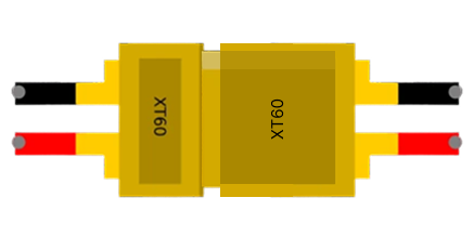
The XT60 connector, manufactured by XT60, is a widely used electrical connector in RC (radio-controlled) applications and other high-current systems. The "female and male combine" refers to the pairing of the female and male connectors, which ensures a secure, reliable, and efficient connection. These connectors are designed to handle high currents (up to 60A) and are commonly used in drones, RC cars, battery packs, and other electronic systems requiring robust power delivery.

Explore Projects Built with Xt60 female and male combine

Use Cirkit Designer to design, explore, and prototype these projects online. Some projects support real-time simulation. Click "Open Project" to start designing instantly!
Satellite-Based Timing and Navigation System with SDR and Atomic Clock Synchronization
Image of GPS 시스템 측정 구성도_Confirm: A project utilizing Xt60 female and male combine in a practical application
This circuit appears to be a complex system involving power supply management, GPS and timing synchronization, and data communication. It includes a SI-TEX G1 Satellite Compass for GPS data, an XHTF1021 Atomic Rubidium Clock for precise timing, and Ettus USRP B200 units for software-defined radio communication. Power is supplied through various SMPS units and distributed via terminal blocks and DC jacks. Data communication is facilitated by Beelink MINI S12 N95 computers, RS232 splitters, and a 1000BASE-T Media Converter for network connectivity. RF Directional Couplers are used to interface antennas with the USRP units, and the entire system is likely contained within cases for protection and organization.
Cirkit Designer LogoOpen Project in Cirkit Designer
Multi-Channel Load Cell Measurement System with JYS60 Amplifiers and DAQ Integration
Image of Load Cell Circuit: A project utilizing Xt60 female and male combine in a practical application
This is a multi-channel load cell measurement system with several JYS60 amplifiers connected to load cells for weight or force sensing. The amplified signals are directed to a DAQ system for data capture, and power is supplied through a barrel jack. Grounding is achieved via an AdaGator Side Black component.
Cirkit Designer LogoOpen Project in Cirkit Designer
FTDI to UART Adapter with J26 Connector
Image of J26 CLOSEUP: A project utilizing Xt60 female and male combine in a practical application
This circuit connects an FTDI USB-to-serial converter to a standard serial interface via a J26 connector. It facilitates serial communication by linking the ground, transmit, receive, data terminal ready, and request to send signals between the FTDI chip and the J26 connector.
Cirkit Designer LogoOpen Project in Cirkit Designer
Cellular-Enabled IoT Device with Real-Time Clock and Power Management
Image of LRCM PHASE 2 BASIC: A project utilizing Xt60 female and male combine in a practical application
This circuit features a LilyGo-SIM7000G module for cellular communication and GPS functionality, interfaced with an RTC DS3231 for real-time clock capabilities. It includes voltage sensing through two voltage sensor modules, and uses an 8-channel opto-coupler for isolating different parts of the circuit. Power management is handled by a buck converter connected to a DC power source and batteries, with a fuse for protection and a rocker switch for on/off control. Additionally, there's an LED for indication purposes.
Cirkit Designer LogoOpen Project in Cirkit Designer

Explore Projects Built with Xt60 female and male combine

Use Cirkit Designer to design, explore, and prototype these projects online. Some projects support real-time simulation. Click "Open Project" to start designing instantly!
Image of GPS 시스템 측정 구성도_Confirm: A project utilizing Xt60 female and male combine in a practical application
Satellite-Based Timing and Navigation System with SDR and Atomic Clock Synchronization
This circuit appears to be a complex system involving power supply management, GPS and timing synchronization, and data communication. It includes a SI-TEX G1 Satellite Compass for GPS data, an XHTF1021 Atomic Rubidium Clock for precise timing, and Ettus USRP B200 units for software-defined radio communication. Power is supplied through various SMPS units and distributed via terminal blocks and DC jacks. Data communication is facilitated by Beelink MINI S12 N95 computers, RS232 splitters, and a 1000BASE-T Media Converter for network connectivity. RF Directional Couplers are used to interface antennas with the USRP units, and the entire system is likely contained within cases for protection and organization.
Cirkit Designer LogoOpen Project in Cirkit Designer
Image of Load Cell Circuit: A project utilizing Xt60 female and male combine in a practical application
Multi-Channel Load Cell Measurement System with JYS60 Amplifiers and DAQ Integration
This is a multi-channel load cell measurement system with several JYS60 amplifiers connected to load cells for weight or force sensing. The amplified signals are directed to a DAQ system for data capture, and power is supplied through a barrel jack. Grounding is achieved via an AdaGator Side Black component.
Cirkit Designer LogoOpen Project in Cirkit Designer
Image of J26 CLOSEUP: A project utilizing Xt60 female and male combine in a practical application
FTDI to UART Adapter with J26 Connector
This circuit connects an FTDI USB-to-serial converter to a standard serial interface via a J26 connector. It facilitates serial communication by linking the ground, transmit, receive, data terminal ready, and request to send signals between the FTDI chip and the J26 connector.
Cirkit Designer LogoOpen Project in Cirkit Designer
Image of LRCM PHASE 2 BASIC: A project utilizing Xt60 female and male combine in a practical application
Cellular-Enabled IoT Device with Real-Time Clock and Power Management
This circuit features a LilyGo-SIM7000G module for cellular communication and GPS functionality, interfaced with an RTC DS3231 for real-time clock capabilities. It includes voltage sensing through two voltage sensor modules, and uses an 8-channel opto-coupler for isolating different parts of the circuit. Power management is handled by a buck converter connected to a DC power source and batteries, with a fuse for protection and a rocker switch for on/off control. Additionally, there's an LED for indication purposes.
Cirkit Designer LogoOpen Project in Cirkit Designer

Common Applications

  • RC vehicles (drones, cars, boats, and planes)
  • Lithium Polymer (LiPo) battery connections
  • High-current power systems
  • DIY electronics projects requiring secure power connections

Technical Specifications

Key Technical Details

Parameter Value
Manufacturer XT60
Manufacturer Part ID XT60
Connector Type Male and Female Pair
Current Rating Up to 60A
Voltage Rating Up to 500V DC
Material Nylon with gold-plated pins
Operating Temperature -20°C to 120°C
Wire Gauge Compatibility 12 AWG to 14 AWG
Dimensions (Combined) 21.6mm x 15.8mm x 8.4mm

Pin Configuration and Descriptions

The XT60 connector consists of two gold-plated pins: one for positive (+) and one for negative (-). The connectors are keyed to prevent reverse polarity.

Female Connector Pinout

Pin Number Function Description
1 Positive (+) Connects to the positive terminal of the power source
2 Negative (-) Connects to the negative terminal of the power source

Male Connector Pinout

Pin Number Function Description
1 Positive (+) Connects to the positive terminal of the load
2 Negative (-) Connects to the negative terminal of the load

Usage Instructions

How to Use the XT60 Connector in a Circuit

  1. Prepare the Wires: Strip the insulation from the wires you intend to connect to the XT60 connector. Ensure the wire gauge is compatible (12 AWG to 14 AWG).
  2. Solder the Wires:
    • Heat the soldering iron to the appropriate temperature.
    • Tin the exposed wire ends and the connector's solder cups with solder.
    • Insert the tinned wire into the solder cup and apply heat until the solder flows and creates a solid connection.
  3. Secure the Connection: Allow the solder to cool and inspect the joint for a clean, shiny finish. Ensure there are no cold solder joints or loose connections.
  4. Assemble the Connector: Slide the heat shrink tubing (if used) over the soldered joint and apply heat to secure it. Connect the male and female connectors to ensure proper alignment and fit.

Important Considerations and Best Practices

  • Polarity: Always double-check the polarity before connecting the XT60 connectors to avoid damage to your circuit.
  • Soldering: Use a high-quality soldering iron and lead-free solder for a reliable connection.
  • Heat Management: Avoid overheating the connector during soldering, as excessive heat can deform the nylon housing.
  • Connection: Ensure the male and female connectors are fully mated to prevent arcing or intermittent connections.
  • Testing: Use a multimeter to verify continuity and polarity after soldering.

Example: Connecting an XT60 to an Arduino UNO

While the XT60 connector itself is not directly connected to an Arduino UNO, it can be used to supply power to the Arduino via a voltage regulator or battery pack. Below is an example of how to use an XT60 connector with a LiPo battery to power an Arduino UNO.

Circuit Diagram

  1. Connect the XT60 female connector to the LiPo battery.
  2. Use a voltage regulator (e.g., LM7805) to step down the voltage to 5V.
  3. Connect the output of the voltage regulator to the Arduino UNO's VIN and GND pins.

Sample Code

// Example code to blink an LED on Arduino UNO
// Ensure the Arduino is powered via the XT60 connector and voltage regulator

void setup() {
  pinMode(13, OUTPUT); // Set pin 13 as an output for the onboard LED
}

void loop() {
  digitalWrite(13, HIGH); // Turn the LED on
  delay(1000);            // Wait for 1 second
  digitalWrite(13, LOW);  // Turn the LED off
  delay(1000);            // Wait for 1 second
}

Troubleshooting and FAQs

Common Issues

  1. Loose Connection:

    • Cause: Improper soldering or incomplete mating of connectors.
    • Solution: Re-solder the connections and ensure the connectors are fully mated.
  2. Overheating During Soldering:

    • Cause: Excessive heat applied to the connector.
    • Solution: Use a temperature-controlled soldering iron and limit the soldering time.
  3. Reverse Polarity:

    • Cause: Incorrect wiring of the positive and negative terminals.
    • Solution: Double-check the polarity before soldering and connecting.
  4. Arcing or Intermittent Connection:

    • Cause: Connectors not fully mated or damaged pins.
    • Solution: Inspect the connectors for damage and ensure a tight fit.

FAQs

Q: Can the XT60 connector handle currents above 60A?
A: While the XT60 is rated for up to 60A, exceeding this limit may cause overheating and damage. For higher currents, consider using connectors like the XT90.

Q: Can I reuse an XT60 connector after desoldering?
A: Yes, but ensure the connector is not damaged or deformed during the desoldering process.

Q: Is the XT60 connector waterproof?
A: No, the XT60 connector is not waterproof. Use additional sealing methods if water resistance is required.

Q: Can I connect an XT60 directly to an Arduino?
A: No, the XT60 is typically used for high-current power delivery. Use a voltage regulator to step down the voltage to a level suitable for the Arduino.

By following this documentation, you can effectively use the XT60 female and male connectors in your projects for secure and reliable power connections.