How to Use Magnetic Contactor: Examples, Pinouts, and Specs
Introduction
A magnetic contactor is an electrically controlled switch designed for switching power circuits, particularly in high-current applications. It operates using an electromagnet that, when energized, pulls a set of contacts together to close the circuit. Magnetic contactors are widely used in industrial and commercial applications due to their reliability, durability, and ability to handle large electrical loads.
Explore Projects Built with Magnetic Contactor


Explore Projects Built with Magnetic Contactor
Common Applications and Use Cases
- Motor control in industrial machinery
- HVAC systems for controlling compressors and fans
- Lighting control in large buildings
- Power distribution systems
- Automation systems for switching high-current loads
Technical Specifications
Below are the general technical specifications for a typical magnetic contactor. Note that specific values may vary depending on the model and manufacturer.
Key Technical Details
- Rated Voltage (Coil): 24V DC, 48V DC, 110V AC, 220V AC, or 380V AC (varies by model)
- Rated Current (Contacts): 9A to 800A (depending on the application)
- Contact Configuration: Normally Open (NO), Normally Closed (NC), or a combination
- Operating Frequency: 50Hz or 60Hz
- Insulation Voltage: Up to 1000V
- Mechanical Life: Typically 10 million operations
- Electrical Life: Typically 1 million operations (under rated load)
- Ambient Temperature Range: -5°C to +55°C
- Mounting: DIN rail or panel mount
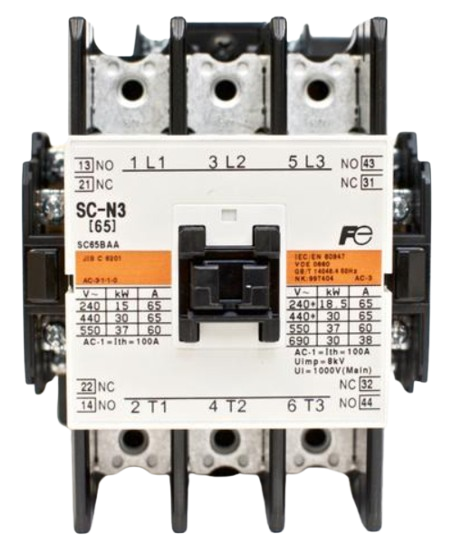
Pin Configuration and Descriptions
The pin configuration of a magnetic contactor typically includes terminals for the coil, main power contacts, and auxiliary contacts. Below is a general description:
| Pin/Terminal | Description |
|---|---|
| A1, A2 | Coil terminals: Used to energize the electromagnet (polarity depends on model). |
| L1, L2, L3 | Input power terminals: Connect to the power source (3-phase or single-phase). |
| T1, T2, T3 | Output power terminals: Connect to the load (e.g., motor, lighting). |
| NO (Auxiliary) | Normally Open auxiliary contact: Used for control or signaling circuits. |
| NC (Auxiliary) | Normally Closed auxiliary contact: Used for control or signaling circuits. |
| Ground (optional) | Grounding terminal for safety (if provided). |
Usage Instructions
How to Use the Component in a Circuit
- Determine the Coil Voltage: Verify the voltage rating of the contactor's coil and ensure it matches the control circuit's voltage.
- Connect the Coil Terminals: Connect the control circuit to the A1 and A2 terminals. For DC coils, ensure correct polarity.
- Connect the Power Terminals:
- Connect the power source to the L1, L2, and L3 terminals (for 3-phase systems) or L1 and L2 (for single-phase systems).
- Connect the load (e.g., motor, lighting) to the T1, T2, and T3 terminals.
- Use Auxiliary Contacts (if needed): Connect auxiliary contacts (NO or NC) to control or signaling circuits as required.
- Secure the Contactor: Mount the contactor on a DIN rail or panel, ensuring proper ventilation and secure connections.
- Test the Circuit: Energize the coil to verify that the contactor operates correctly and switches the load.
Important Considerations and Best Practices
- Overload Protection: Always use an appropriate overload relay or circuit breaker to protect the load and contactor.
- Voltage Matching: Ensure the coil voltage and power circuit voltage match the contactor's specifications.
- Avoid Overheating: Do not exceed the rated current or voltage to prevent overheating and damage.
- Regular Maintenance: Periodically inspect the contactor for wear, dirt, or loose connections.
- Noise Suppression: For DC coils, consider adding a flyback diode across the coil terminals to suppress voltage spikes.
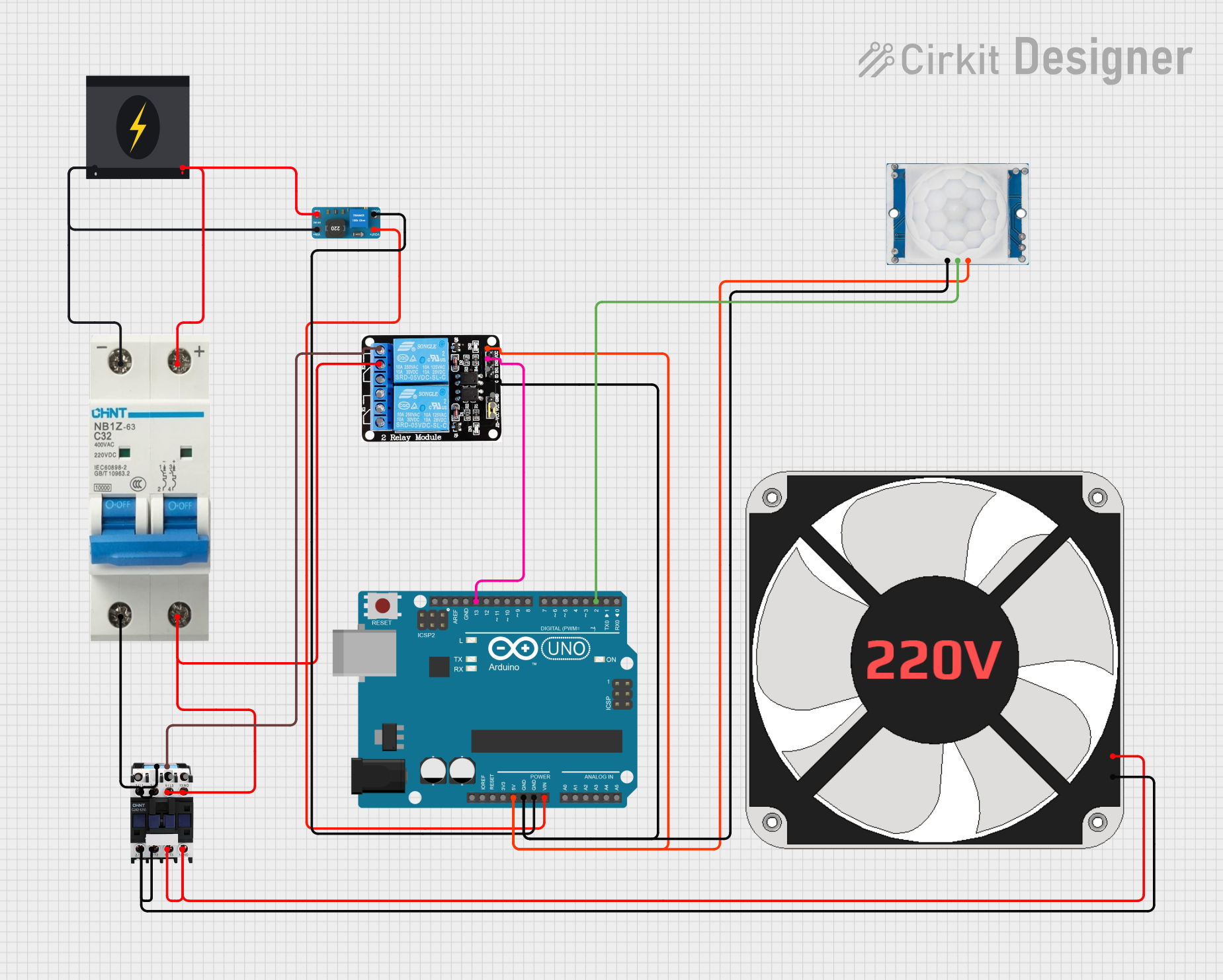
Example: Connecting a Magnetic Contactor to an Arduino UNO
You can use an Arduino UNO to control a magnetic contactor via a relay module. Below is an example code snippet:
// Magnetic Contactor Control with Arduino UNO
// This code uses a relay module to control the contactor's coil.

const int relayPin = 7; // Pin connected to the relay module

void setup() {
  pinMode(relayPin, OUTPUT); // Set relay pin as output
  digitalWrite(relayPin, LOW); // Ensure relay is off at startup
}

void loop() {
  // Turn on the contactor
  digitalWrite(relayPin, HIGH); // Energize the relay to close the contactor
  delay(5000); // Keep the contactor on for 5 seconds

  // Turn off the contactor
  digitalWrite(relayPin, LOW); // De-energize the relay to open the contactor
  delay(5000); // Wait for 5 seconds before repeating
}
Note: Ensure the relay module is rated to handle the contactor's coil voltage and current. Use an external power supply for the relay module if necessary.
Troubleshooting and FAQs
Common Issues and Solutions
Contactor Does Not Energize:
- Cause: Incorrect coil voltage or loose connections.
- Solution: Verify the coil voltage matches the control circuit and check all connections.
Contacts Overheat:
- Cause: Exceeding the rated current or poor ventilation.
- Solution: Ensure the load current is within the contactor's rating and provide adequate ventilation.
Chattering Noise:
- Cause: Insufficient coil voltage or fluctuating power supply.
- Solution: Check the power supply and ensure stable voltage to the coil.
Auxiliary Contacts Not Working:
- Cause: Miswiring or damaged contacts.
- Solution: Verify the wiring and inspect the auxiliary contacts for wear or damage.
Contactor Fails to Release:
- Cause: Mechanical sticking or residual magnetism.
- Solution: Inspect the contactor for mechanical issues and clean any debris.
FAQs
Q: Can I use a magnetic contactor for DC loads?
A: Yes, but ensure the contactor is specifically rated for DC applications, as DC arcs are harder to extinguish than AC arcs.Q: How do I select the right contactor for my application?
A: Consider the load's voltage, current, and type (AC or DC), as well as the control circuit's voltage.Q: Can I mount the contactor in any orientation?
A: Most contactors can be mounted in any orientation, but refer to the manufacturer's guidelines for specific recommendations.Q: What is the difference between a relay and a contactor?
A: A relay is designed for low-current applications, while a contactor is built to handle high-current loads.
By following this documentation, you can effectively use and troubleshoot a magnetic contactor in your projects.