How to Use ZK-502L: Examples, Pinouts, and Specs
Introduction
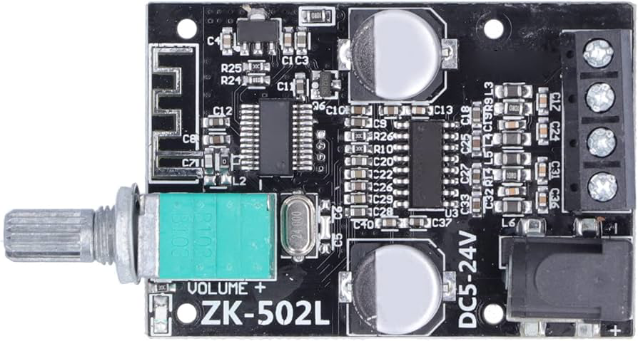
The ZK-502L, manufactured by Walfront, is a compact, low-power relay designed for efficient switching in electronic circuits. It features a Single Pole Double Throw (SPDT) configuration, enabling it to control multiple circuits with a single input signal. This relay is ideal for applications requiring reliable switching with minimal power consumption.
Explore Projects Built with ZK-502L


Explore Projects Built with ZK-502L
Common Applications and Use Cases
- Home automation systems
- Industrial control panels
- Motor control circuits
- Signal switching in low-power devices
- DIY electronics and prototyping
Technical Specifications
Key Technical Details
| Parameter | Value |
|---|---|
| Manufacturer Part ID | ZK‑502L |
| Configuration | SPDT (Single Pole Double Throw) |
| Operating Voltage | 5V DC |
| Coil Resistance | 70 Ω |
| Switching Voltage | Up to 250V AC / 30V DC |
| Switching Current | Up to 10A |
| Power Consumption | 0.36W |
| Contact Material | Silver alloy |
| Dimensions | 19mm x 15mm x 15mm |
| Weight | 10g |
Pin Configuration and Descriptions
The ZK-502L relay has 5 pins. Below is the pinout and description:
| Pin Number | Name | Description |
|---|---|---|
| 1 | Coil (+) | Positive terminal of the relay coil. Connect to the control voltage (5V DC). |
| 2 | Coil (-) | Negative terminal of the relay coil. Connect to ground. |
| 3 | Common (COM) | Common terminal for the switching circuit. |
| 4 | Normally Open (NO) | Open circuit when the relay is inactive; closes when the relay is activated. |
| 5 | Normally Closed (NC) | Closed circuit when the relay is inactive; opens when the relay is activated. |
Usage Instructions
How to Use the ZK-502L in a Circuit
- Power the Relay Coil: Connect the Coil (+) pin to a 5V DC power source and the Coil (-) pin to ground. This energizes the relay coil and switches the contacts.
- Connect the Load:
- For devices that should turn on when the relay is activated, connect the load between the Common (COM) and Normally Open (NO) pins.
- For devices that should turn off when the relay is activated, connect the load between the Common (COM) and Normally Closed (NC) pins.
- Control the Relay: Use a microcontroller (e.g., Arduino UNO) or a manual switch to control the relay coil.
Important Considerations and Best Practices
- Diode Protection: Always connect a flyback diode (e.g., 1N4007) across the relay coil to protect the circuit from voltage spikes when the relay is de-energized.
- Power Ratings: Ensure the load connected to the relay does not exceed its maximum voltage (250V AC / 30V DC) or current (10A) ratings.
- Isolation: Use optocouplers or transistors to isolate the relay from sensitive control circuits if needed.
- Mounting: Secure the relay on a PCB or relay socket to ensure stable operation.
Example: Using ZK-502L with Arduino UNO
Below is an example of how to control the ZK-502L relay using an Arduino UNO:
// Example: Controlling ZK-502L Relay with Arduino UNO

const int relayPin = 7; // Pin connected to the relay's Coil (+)

void setup() {
  pinMode(relayPin, OUTPUT); // Set relay pin as output
  digitalWrite(relayPin, LOW); // Ensure relay is off at startup
}

void loop() {
  digitalWrite(relayPin, HIGH); // Activate the relay
  delay(1000); // Keep relay on for 1 second
  digitalWrite(relayPin, LOW); // Deactivate the relay
  delay(1000); // Keep relay off for 1 second
}
Note: Use a transistor (e.g., 2N2222) to drive the relay if the Arduino pin cannot supply sufficient current.
Troubleshooting and FAQs
Common Issues and Solutions
Relay Not Activating:
- Cause: Insufficient voltage or current to the relay coil.
- Solution: Verify the power supply provides 5V DC and sufficient current (at least 72mA).
Voltage Spikes Damaging Circuit:
- Cause: Lack of a flyback diode across the relay coil.
- Solution: Install a flyback diode (e.g., 1N4007) across the coil terminals.
Load Not Switching Properly:
- Cause: Incorrect wiring of the load to the relay pins.
- Solution: Double-check the connections to the COM, NO, and NC pins.
Relay Heating Up:
- Cause: Exceeding the relay's power or current ratings.
- Solution: Ensure the load does not exceed 10A or the specified voltage limits.
FAQs
Q1: Can the ZK-502L relay be used with a 3.3V control signal?
A1: No, the ZK-502L requires a 5V DC control signal to activate the coil. Use a level shifter or transistor to interface with 3.3V systems.
Q2: Is the ZK-502L suitable for high-frequency switching?
A2: No, mechanical relays like the ZK-502L are not designed for high-frequency switching. Consider using a solid-state relay (SSR) for such applications.
Q3: Can I use the ZK-502L to switch AC loads?
A3: Yes, the ZK-502L can switch AC loads up to 250V, provided the current does not exceed 10A.
Q4: How do I know if the relay is activated?
A4: You can hear a clicking sound when the relay switches. Alternatively, you can measure continuity between the COM and NO pins to confirm activation.