How to Use MAX30205: Examples, Pinouts, and Specs
Introduction
The MAX30205 is a high-accuracy digital temperature sensor that provides a 12-bit temperature reading via an I2C interface. Designed specifically for medical applications, it offers exceptional precision and low power consumption, making it ideal for body temperature monitoring. Its compact design and ease of integration also make it suitable for wearable devices, industrial temperature sensing, and other applications requiring precise temperature measurements.
Explore Projects Built with MAX30205

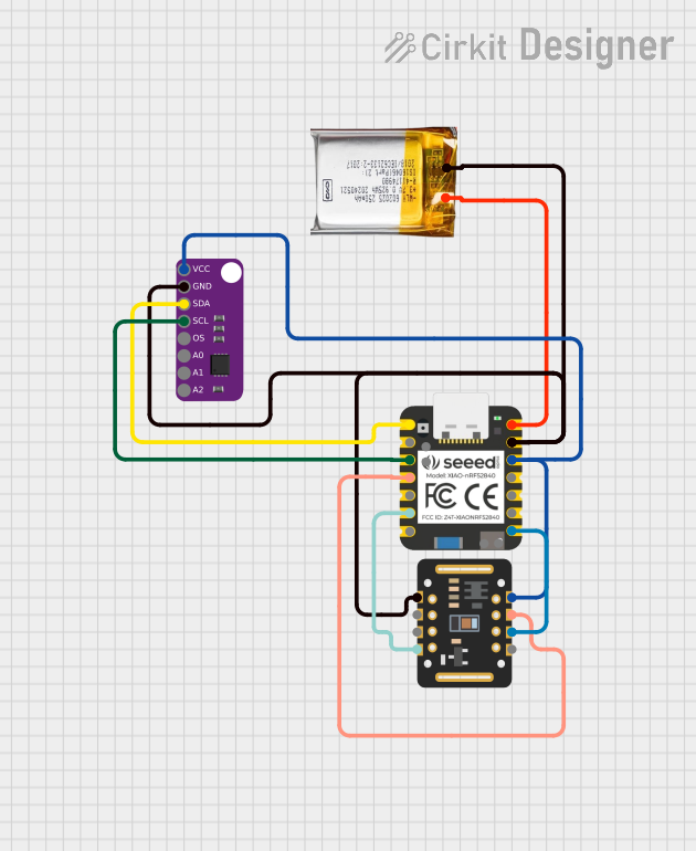
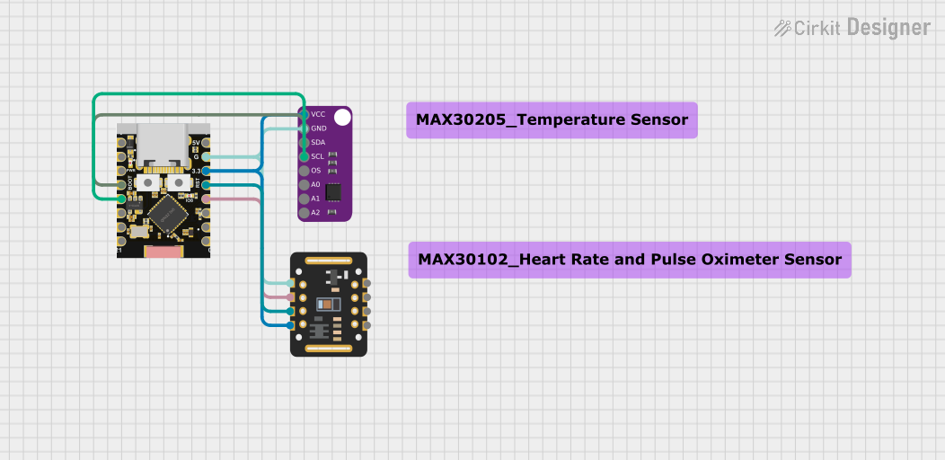

Explore Projects Built with MAX30205
Common Applications:
- Body temperature monitoring in medical devices
- Wearable health and fitness trackers
- Industrial temperature sensing
- Environmental monitoring systems
- IoT devices requiring accurate temperature data
Technical Specifications
The MAX30205 is designed to deliver reliable and accurate temperature readings with minimal power consumption. Below are its key technical details:
Key Specifications:
| Parameter | Value |
|---|---|
| Supply Voltage (VDD) | 2.7V to 3.3V |
| Temperature Range | 0°C to +50°C (medical accuracy) |
| Accuracy | ±0.1°C (human body temperature) |
| Resolution | 12-bit (0.00390625°C per LSB) |
| Interface | I2C (up to 400kHz) |
| Current Consumption | 600µA (typical) |
| Shutdown Current | 0.1µA (typical) |
| Package | 8-pin TDFN (2mm x 2mm) |
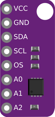
Pin Configuration:
The MAX30205 comes in an 8-pin TDFN package. Below is the pinout and description:
| Pin Number | Pin Name | Description |
|---|---|---|
| 1 | SDA | I2C Data Line |
| 2 | SCL | I2C Clock Line |
| 3 | ALERT | Overtemperature Alert Output (Open-Drain) |
| 4 | GND | Ground |
| 5 | VDD | Power Supply (2.7V to 3.3V) |
| 6 | NC | No Connection |
| 7 | NC | No Connection |
| 8 | NC | No Connection |
Usage Instructions
The MAX30205 is straightforward to use in a circuit, thanks to its I2C interface. Below are the steps and considerations for integrating it into your design:
Circuit Connection:
- Power Supply: Connect the VDD pin to a 3.3V power source and the GND pin to ground.
- I2C Interface: Connect the SDA and SCL pins to the corresponding I2C data and clock lines of your microcontroller. Use pull-up resistors (typically 4.7kΩ) on both lines.
- Alert Pin (Optional): The ALERT pin can be connected to a microcontroller GPIO pin to monitor overtemperature conditions. If unused, leave it unconnected.
- Bypass Capacitor: Place a 0.1µF ceramic capacitor close to the VDD pin for power supply decoupling.
Arduino UNO Example Code:
Below is an example of how to interface the MAX30205 with an Arduino UNO to read temperature data:
#include <Wire.h>

// MAX30205 I2C address
#define MAX30205_ADDRESS 0x48

void setup() {
  Wire.begin(); // Initialize I2C communication
  Serial.begin(9600); // Initialize serial communication for debugging

  // Configure MAX30205 (optional, as it works with default settings)
  Wire.beginTransmission(MAX30205_ADDRESS);
  Wire.write(0x01); // Access configuration register
  Wire.write(0x00); // Set to default configuration
  Wire.endTransmission();
}

void loop() {
  float temperature = readTemperature();
  Serial.print("Temperature: ");
  Serial.print(temperature);
  Serial.println(" °C");
  delay(1000); // Wait 1 second before the next reading
}

float readTemperature() {
  Wire.beginTransmission(MAX30205_ADDRESS);
  Wire.write(0x00); // Access temperature register
  Wire.endTransmission();

  Wire.requestFrom(MAX30205_ADDRESS, 2); // Request 2 bytes of data
  if (Wire.available() == 2) {
    uint8_t msb = Wire.read(); // Most significant byte
    uint8_t lsb = Wire.read(); // Least significant byte

    // Combine MSB and LSB into a 16-bit value
    int16_t rawTemperature = (msb << 8) | lsb;

    // Convert to Celsius (12-bit resolution)
    return rawTemperature * 0.00390625;
  }
  return -999.0; // Return error value if data is unavailable
}
Important Considerations:
- I2C Pull-Up Resistors: Ensure proper pull-up resistors are used on the SDA and SCL lines.
- Power Supply: Use a stable 3.3V power source to avoid measurement inaccuracies.
- Alert Pin: Configure the ALERT pin if you need to monitor overtemperature conditions.
- Temperature Range: For medical applications, ensure the operating temperature is within 0°C to +50°C for optimal accuracy.
Troubleshooting and FAQs
Common Issues:
No Temperature Reading:
- Cause: Incorrect I2C address or wiring.
- Solution: Verify the MAX30205 I2C address (default is 0x48) and check SDA/SCL connections.
Inaccurate Temperature Measurements:
- Cause: Unstable power supply or incorrect pull-up resistor values.
- Solution: Use a stable 3.3V power source and 4.7kΩ pull-up resistors on SDA and SCL.
ALERT Pin Not Functioning:
- Cause: ALERT pin not configured or connected.
- Solution: Ensure the ALERT pin is connected to a GPIO pin and properly configured in your code.
Device Not Detected on I2C Bus:
- Cause: Conflicting I2C addresses or missing pull-up resistors.
- Solution: Check for address conflicts and ensure pull-up resistors are present.
FAQs:
Q1: Can the MAX30205 operate at 5V?
A1: No, the MAX30205 operates within a supply voltage range of 2.7V to 3.3V. Using 5V may damage the device.
Q2: What is the maximum I2C clock speed supported?
A2: The MAX30205 supports I2C clock speeds up to 400kHz.
Q3: How do I ensure medical-grade accuracy?
A3: Operate the sensor within the 0°C to +50°C range and use a stable power supply for optimal accuracy.
Q4: Can I use the MAX30205 for non-medical applications?
A4: Yes, the MAX30205 is suitable for any application requiring precise temperature measurements.