Cirkit Designer
Your all-in-one circuit design IDE
Home /
Component Documentation
How to Use Relevo 4 canales: Examples, Pinouts, and Specs
Introduction
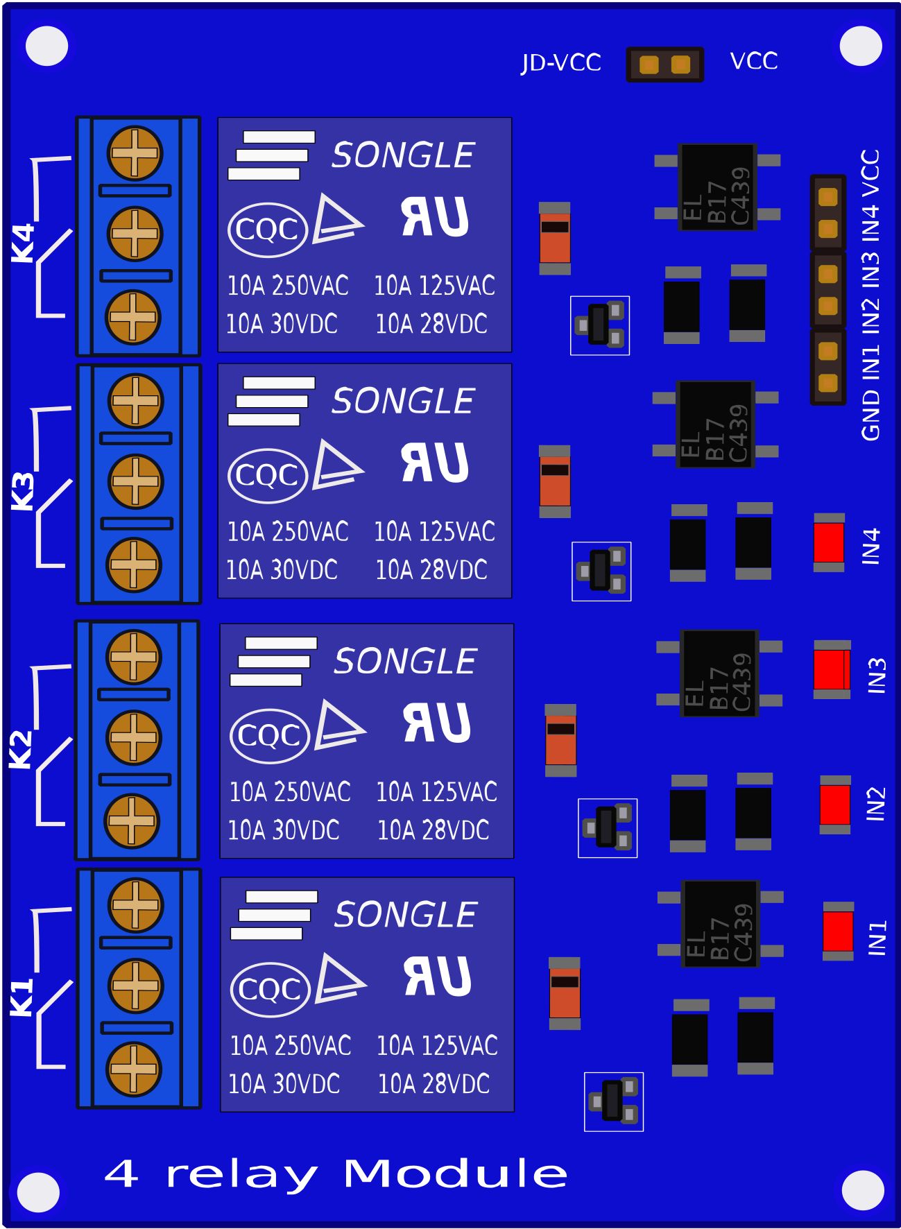
The Relevo 4 Canales is a module that contains four relays, allowing the control of four independent circuits using low-power signals. This component is widely used in applications where it is necessary to control high-power devices with a microcontroller or other low-power control systems. Common use cases include home automation, industrial control systems, and robotics.
Explore Projects Built with Relevo 4 canales
ESP32-Controlled 4-Channel Relay Module
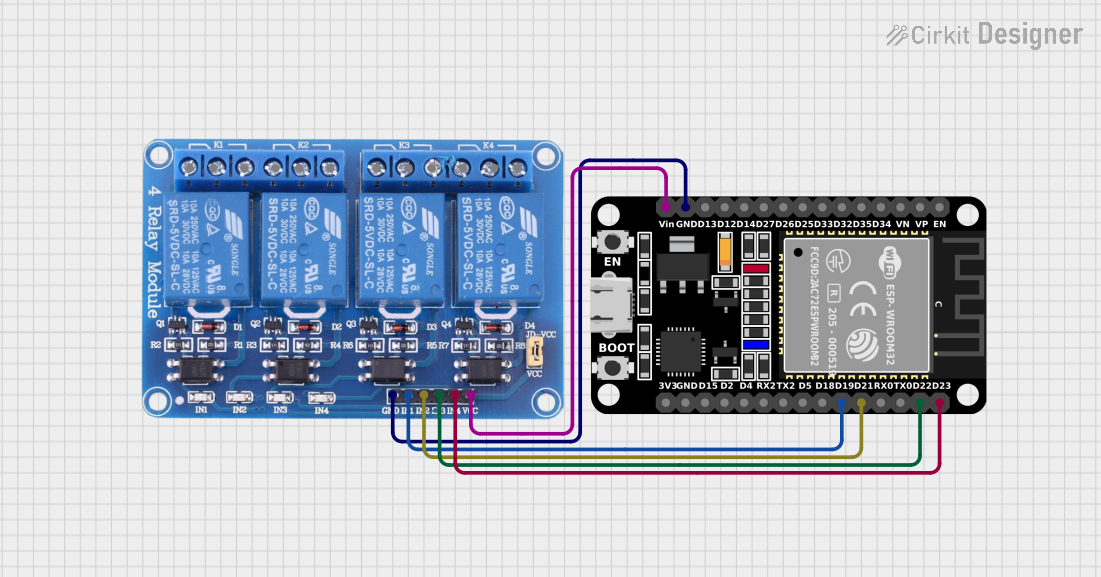
This circuit connects an ESP32 microcontroller to a 4-channel 5V relay module. The ESP32's digital pins (D19, D21, D22, D23) are used to control the relay channels (IN1, IN2, IN3, IN4) respectively. The circuit is designed to allow the ESP32 to switch external devices on and off via the relay module.
Arduino-Controlled Relay Switch with Pushbutton Activation

This circuit utilizes a 4-channel relay module controlled by an Arduino UNO, allowing for the switching of multiple devices based on input from several pushbuttons. Each pushbutton can activate a corresponding relay channel, which can be used to control various loads, while LEDs provide visual feedback for the relay states.
Battery-Powered 4-Channel Relay Control with LED Indicators

This circuit consists of a 5V battery powering a 4-channel relay module, which controls four LEDs (red, yellow, green, and blue) through individual resistors. Each relay channel is activated by a corresponding SPST toggle switch, allowing manual control of the LEDs.
Arduino-Controlled Soundwave Generator with IR Sensor Activation and LCD Feedback
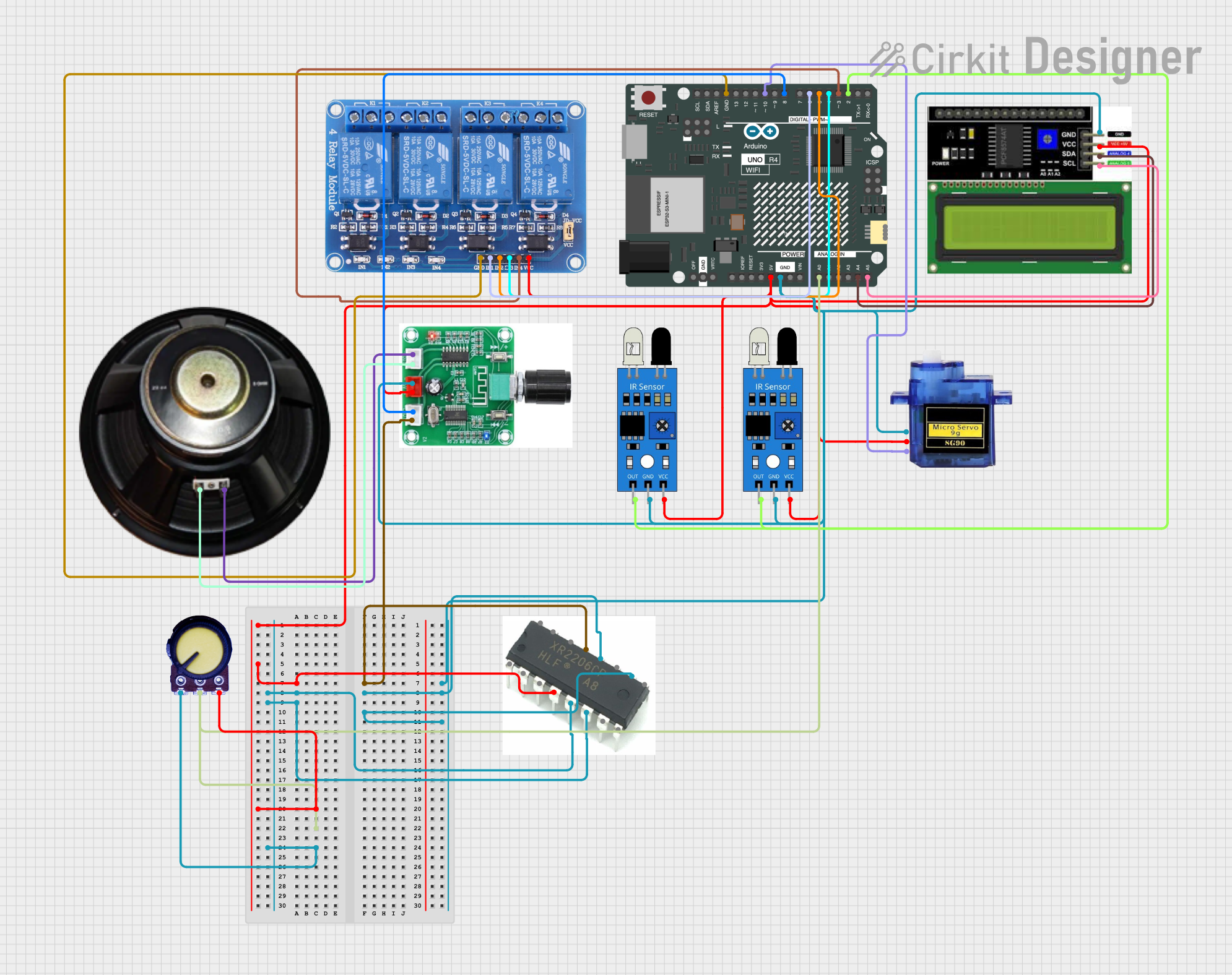
This circuit features an Arduino UNO R4 WiFi microcontroller programmed to control a 4-channel relay, read from two IR sensors, and adjust a micro servo's position based on the IR sensors' input. It also generates variable frequency sound waves through a speaker using an XR2206 function generator, with the frequency adjusted by a potentiometer. An LCD I2C display is used to show the frequency and IR sensor status, and the sound's volume is controlled by a PAM8403 amplifier.
Explore Projects Built with Relevo 4 canales
ESP32-Controlled 4-Channel Relay Module
This circuit connects an ESP32 microcontroller to a 4-channel 5V relay module. The ESP32's digital pins (D19, D21, D22, D23) are used to control the relay channels (IN1, IN2, IN3, IN4) respectively. The circuit is designed to allow the ESP32 to switch external devices on and off via the relay module.
Arduino-Controlled Relay Switch with Pushbutton Activation
This circuit utilizes a 4-channel relay module controlled by an Arduino UNO, allowing for the switching of multiple devices based on input from several pushbuttons. Each pushbutton can activate a corresponding relay channel, which can be used to control various loads, while LEDs provide visual feedback for the relay states.
Battery-Powered 4-Channel Relay Control with LED Indicators
This circuit consists of a 5V battery powering a 4-channel relay module, which controls four LEDs (red, yellow, green, and blue) through individual resistors. Each relay channel is activated by a corresponding SPST toggle switch, allowing manual control of the LEDs.
Arduino-Controlled Soundwave Generator with IR Sensor Activation and LCD Feedback
This circuit features an Arduino UNO R4 WiFi microcontroller programmed to control a 4-channel relay, read from two IR sensors, and adjust a micro servo's position based on the IR sensors' input. It also generates variable frequency sound waves through a speaker using an XR2206 function generator, with the frequency adjusted by a potentiometer. An LCD I2C display is used to show the frequency and IR sensor status, and the sound's volume is controlled by a PAM8403 amplifier.
Technical Specifications
Key Technical Details
| Parameter | Value |
|---|---|
| Operating Voltage | 5V DC |
| Trigger Voltage | 3.3V - 5V DC |
| Relay Type | SPDT (Single Pole Double Throw) |
| Max Switching Voltage | 250V AC / 30V DC |
| Max Switching Current | 10A |
| Number of Channels | 4 |
| Dimensions | 75mm x 55mm x 19mm |
Pin Configuration and Descriptions
Input Pins
| Pin Name | Description |
|---|---|
| VCC | Power supply (5V DC) |
| GND | Ground |
| IN1 | Control signal for Relay 1 (Active Low) |
| IN2 | Control signal for Relay 2 (Active Low) |
| IN3 | Control signal for Relay 3 (Active Low) |
| IN4 | Control signal for Relay 4 (Active Low) |
Output Pins (Relay Terminals)
| Relay | NO (Normally Open) | COM (Common) | NC (Normally Closed) |
|---|---|---|---|
| Relay 1 | NO1 | COM1 | NC1 |
| Relay 2 | NO2 | COM2 | NC2 |
| Relay 3 | NO3 | COM3 | NC3 |
| Relay 4 | NO4 | COM4 | NC4 |
Usage Instructions
How to Use the Component in a Circuit
- Power Supply: Connect the VCC pin to a 5V DC power supply and the GND pin to the ground of your circuit.
- Control Signals: Connect the IN1, IN2, IN3, and IN4 pins to the digital output pins of your microcontroller (e.g., Arduino UNO).
- Relay Outputs: Connect the devices you want to control to the relay terminals (NO, COM, NC) according to your requirements.
Important Considerations and Best Practices
- Isolation: Ensure proper isolation between the low-power control side and the high-power relay side to prevent damage to your microcontroller.
- Flyback Diode: Use flyback diodes across relay coils to protect against voltage spikes.
- Current Rating: Do not exceed the maximum current rating of 10A for each relay.
- Active Low: The control signals are active low, meaning the relay is activated when the control pin is pulled to ground.
Example: Connecting to an Arduino UNO
// Example code to control a 4-channel relay module with Arduino UNO

// Define relay control pins
const int relay1 = 2;
const int relay2 = 3;
const int relay3 = 4;
const int relay4 = 5;

void setup() {
  // Initialize relay control pins as outputs
  pinMode(relay1, OUTPUT);
  pinMode(relay2, OUTPUT);
  pinMode(relay3, OUTPUT);
  pinMode(relay4, OUTPUT);

  // Turn off all relays at the start
  digitalWrite(relay1, HIGH);
  digitalWrite(relay2, HIGH);
  digitalWrite(relay3, HIGH);
  digitalWrite(relay4, HIGH);
}

void loop() {
  // Example sequence to turn on and off relays
  digitalWrite(relay1, LOW);  // Turn on Relay 1
  delay(1000);                // Wait for 1 second
  digitalWrite(relay1, HIGH); // Turn off Relay 1
  delay(1000);                // Wait for 1 second

  digitalWrite(relay2, LOW);  // Turn on Relay 2
  delay(1000);                // Wait for 1 second
  digitalWrite(relay2, HIGH); // Turn off Relay 2
  delay(1000);                // Wait for 1 second

  digitalWrite(relay3, LOW);  // Turn on Relay 3
  delay(1000);                // Wait for 1 second
  digitalWrite(relay3, HIGH); // Turn off Relay 3
  delay(1000);                // Wait for 1 second

  digitalWrite(relay4, LOW);  // Turn on Relay 4
  delay(1000);                // Wait for 1 second
  digitalWrite(relay4, HIGH); // Turn off Relay 4
  delay(1000);                // Wait for 1 second
}
Troubleshooting and FAQs
Common Issues Users Might Face
- Relays Not Activating: Ensure that the control signals are correctly connected and that the VCC and GND pins are properly powered.
- Noise and Interference: Use proper decoupling capacitors and ensure good grounding practices to minimize noise.
- Overheating: Do not exceed the maximum current rating of the relays. Use heat sinks if necessary.
Solutions and Tips for Troubleshooting
- Check Connections: Verify all connections, especially the control signals and power supply.
- Use a Multimeter: Measure the voltage at the control pins to ensure they are being pulled low correctly.
- Inspect for Damage: Look for any visible damage on the module or relays that might indicate a failure.
By following this documentation, users should be able to effectively integrate and utilize the Relevo 4 Canales module in their projects, ensuring reliable and efficient control of multiple circuits.