How to Use SIM800L v2: Examples, Pinouts, and Specs
Introduction
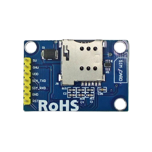
The SIM800L v2 is a compact GSM/GPRS module manufactured by Maker Lab (Part ID: Sim Module). This module enables communication over cellular networks, supporting functionalities such as SMS, voice calls, and data transmission. It is widely used in IoT applications, including remote monitoring, smart home systems, and GPS tracking, due to its small size and low power consumption.
Explore Projects Built with SIM800L v2


Explore Projects Built with SIM800L v2
Common Applications
- Sending and receiving SMS messages
- Making and receiving voice calls
- Transmitting data over GPRS for IoT devices
- GPS tracking and location-based services
- Remote monitoring and control systems
Technical Specifications
Key Technical Details
| Parameter | Value |
|---|---|
| Operating Voltage | 3.4V to 4.4V |
| Recommended Voltage | 4.0V |
| Current Consumption | Idle: ~1mA, Max: ~2A |
| Frequency Bands | GSM 850/900/1800/1900 MHz |
| Communication Protocols | AT Commands (via UART) |
| Data Transmission | GPRS Class 12, up to 85.6 kbps |
| SIM Card Support | Micro SIM |
| Dimensions | 25mm x 23mm x 3mm |
| Operating Temperature | -40°C to +85°C |
Pin Configuration and Descriptions
The SIM800L v2 module has 8 pins. Below is the pinout and description:
| Pin Name | Pin Number | Description |
|---|---|---|
| VCC | 1 | Power input (3.4V to 4.4V). Use a stable power source to avoid resets. |
| GND | 2 | Ground connection. |
| TXD | 3 | UART Transmit pin. Connect to the RX pin of the microcontroller. |
| RXD | 4 | UART Receive pin. Connect to the TX pin of the microcontroller. |
| RST | 5 | Reset pin. Active low. Pull low for 100ms to reset the module. |
| NET | 6 | Network status LED output. Blinks to indicate GSM network status. |
| DTR | 7 | Data Terminal Ready. Used for sleep mode control (optional). |
| MIC+ | 8 | Microphone positive input for voice call applications. |
Usage Instructions
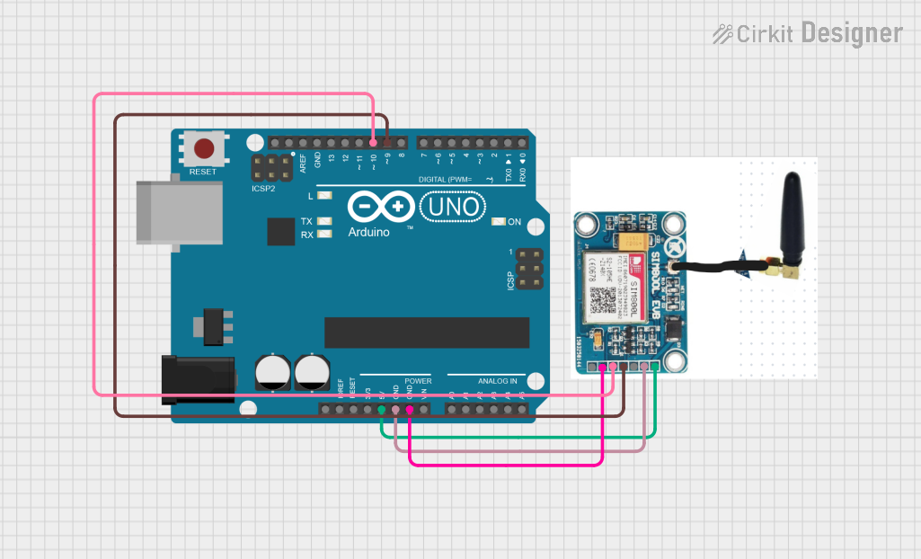
How to Use the SIM800L v2 in a Circuit
Power Supply:
- Use a regulated power supply capable of providing 4.0V and at least 2A of current.
- A capacitor (e.g., 1000µF) is recommended across the power supply to handle voltage drops during high current usage.
Connections:
- Connect the VCC and GND pins to the power supply.
- Connect the TXD and RXD pins to the microcontroller's UART pins (e.g., Arduino UNO). Use a voltage divider or level shifter if the microcontroller operates at 5V logic.
- Optionally, connect the RST pin to a GPIO pin for software-controlled resets.
Antenna:
- Attach an external GSM antenna to the module for better signal reception.
SIM Card:
- Insert a micro SIM card with an active GSM plan into the SIM card slot.
Communication:
- Use AT commands to communicate with the module via UART. For example, send
ATto check if the module is responsive.
- Use AT commands to communicate with the module via UART. For example, send
Important Considerations and Best Practices
- Ensure the power supply is stable and capable of handling peak current demands (~2A).
- Place the module in an area with good GSM signal reception.
- Avoid placing the module near high-frequency noise sources to prevent interference.
- Use proper UART baud rates (default: 9600 bps) for communication.
- Handle the module carefully to avoid damage to the SIM card slot or antenna connector.
Example: Using SIM800L v2 with Arduino UNO
Below is an example code to send an SMS using the SIM800L v2 module:
#include <SoftwareSerial.h>

// Define RX and TX pins for SoftwareSerial
SoftwareSerial sim800l(10, 11); // RX = Pin 10, TX = Pin 11

void setup() {
  // Initialize serial communication
  Serial.begin(9600); // For debugging
  sim800l.begin(9600); // For SIM800L communication

  // Wait for the module to initialize
  delay(1000);
  Serial.println("Initializing SIM800L...");

  // Send AT command to check module response
  sim800l.println("AT");
  delay(1000);
  while (sim800l.available()) {
    Serial.write(sim800l.read()); // Print module response
  }

  // Set SMS text mode
  sim800l.println("AT+CMGF=1"); // Set SMS mode to text
  delay(1000);

  // Send SMS command
  sim800l.println("AT+CMGS=\"+1234567890\""); // Replace with recipient's number
  delay(1000);
  sim800l.println("Hello from SIM800L!"); // SMS content
  delay(1000);
  sim800l.write(26); // Send Ctrl+Z to send the SMS
  delay(5000);

  Serial.println("SMS sent!");
}

void loop() {
  // No actions in loop
}
Notes:
- Replace
+1234567890with the recipient's phone number. - Ensure the Arduino is powered by an external power source if the SIM800L draws high current.
Troubleshooting and FAQs
Common Issues and Solutions
Module Keeps Resetting:
- Ensure the power supply provides at least 2A of current.
- Add a capacitor (e.g., 1000µF) across the power supply to stabilize voltage.
No Response to AT Commands:
- Check the UART connections (TXD and RXD). Ensure they are not swapped.
- Verify the baud rate (default: 9600 bps).
- Ensure the SIM card is properly inserted and activated.
No Network Connection:
- Check the antenna connection.
- Ensure the SIM card has an active GSM plan.
- Place the module in an area with good signal reception.
SMS Not Sending:
- Verify the recipient's phone number format (e.g., include the country code).
- Ensure the SIM card has sufficient balance for sending SMS.
FAQs
Q: Can the SIM800L v2 work with 5V logic microcontrollers?
A: Yes, but you need a voltage divider or level shifter for the RXD pin to avoid damage.Q: What is the maximum data rate for GPRS?
A: The SIM800L supports GPRS Class 12 with a maximum data rate of 85.6 kbps.Q: Can I use the module for GPS tracking?
A: The SIM800L does not have built-in GPS but can work with external GPS modules for location-based services.Q: How do I reset the module?
A: Pull the RST pin low for 100ms and then release it to reset the module.
By following this documentation, users can effectively integrate the SIM800L v2 module into their projects for reliable GSM/GPRS communication.