How to Use Infrared Proximity Sensor: Examples, Pinouts, and Specs

Introduction
The Infrared Proximity Sensor is a device that detects the presence of nearby objects by emitting infrared (IR) light and measuring the reflected signal. It is widely used in applications where non-contact object detection is required. This sensor is commonly found in automation systems, robotics, obstacle detection, and touchless interfaces.
Explore Projects Built with Infrared Proximity Sensor


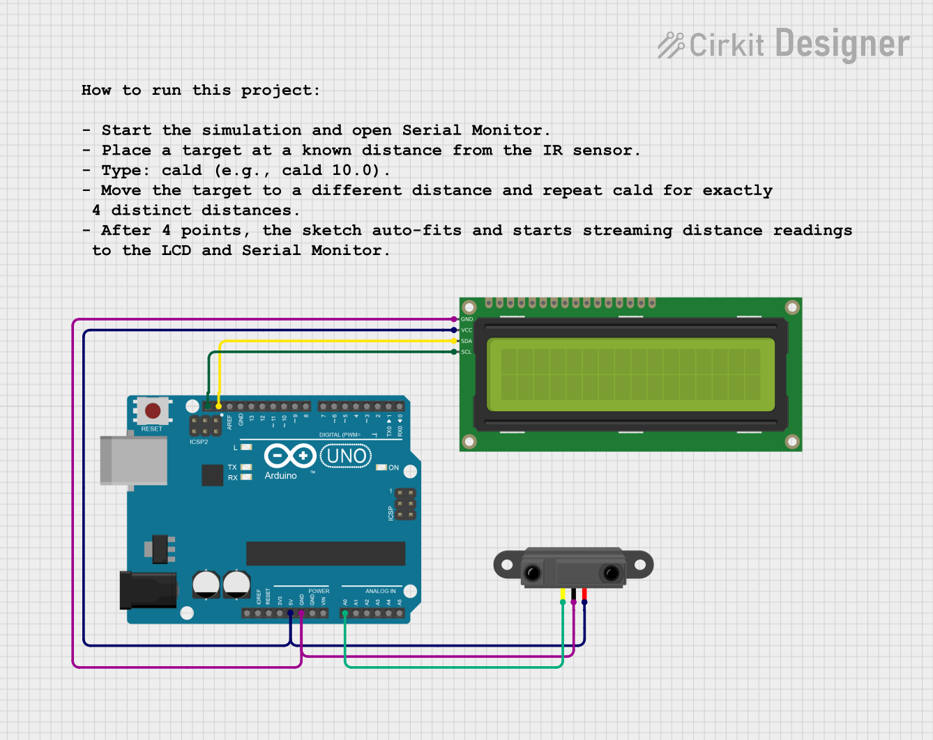
Explore Projects Built with Infrared Proximity Sensor
Common Applications:
- Obstacle detection in robotics
- Automatic doors and hand sanitizers
- Line-following robots
- Proximity-based lighting systems
- Industrial automation for object counting or sorting
Technical Specifications
Below are the key technical details of a typical Infrared Proximity Sensor:
| Parameter | Value |
|---|---|
| Operating Voltage | 3.3V to 5V |
| Operating Current | 20mA to 50mA |
| Detection Range | 2cm to 30cm (varies by model) |
| Output Type | Digital (High/Low) or Analog |
| Wavelength of IR Light | ~940nm |
| Response Time | < 2ms |
| Operating Temperature | -10°C to 50°C |
Pin Configuration and Descriptions
The Infrared Proximity Sensor typically has three or more pins. Below is a table describing the common pinout:
| Pin Name | Description |
|---|---|
| VCC | Power supply pin (3.3V or 5V) |
| GND | Ground connection |
| OUT | Output pin (Digital or Analog signal) |
| EN (optional) | Enable pin to activate or deactivate the sensor |
Usage Instructions
How to Use the Infrared Proximity Sensor in a Circuit
- Power the Sensor: Connect the
VCCpin to a 3.3V or 5V power source and theGNDpin to the ground. - Connect the Output: Attach the
OUTpin to a microcontroller's input pin (e.g., Arduino) or directly to an LED/buzzer for simple applications. - Adjust Sensitivity (if applicable): Some sensors have a potentiometer to adjust the detection range. Turn the potentiometer clockwise or counterclockwise to fine-tune the sensitivity.
- Read the Output: The sensor outputs a HIGH signal when an object is detected within its range and a LOW signal otherwise. For analog sensors, the output voltage varies with the distance of the object.
Important Considerations and Best Practices
- Avoid Ambient Light Interference: Strong ambient light, such as sunlight, can interfere with the sensor's performance. Use the sensor in controlled lighting conditions or shield it from direct light.
- Optimal Placement: Ensure the sensor is mounted at an appropriate angle and distance from the target object for accurate detection.
- Power Supply Stability: Use a stable power source to avoid erratic behavior.
- Testing Range: Test the sensor's range and adjust the sensitivity to suit your application.
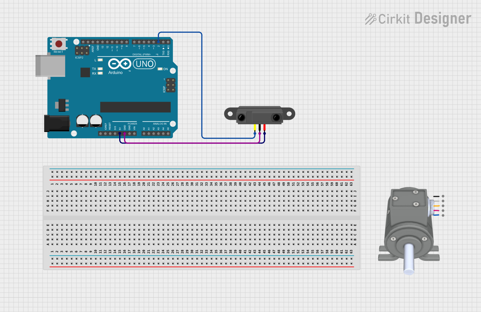
Example: Connecting to an Arduino UNO
Below is an example of how to connect and use the Infrared Proximity Sensor with an Arduino UNO:
Circuit Diagram
- Connect the
VCCpin of the sensor to the 5V pin on the Arduino. - Connect the
GNDpin of the sensor to the GND pin on the Arduino. - Connect the
OUTpin of the sensor to digital pin 2 on the Arduino.
Arduino Code
// Infrared Proximity Sensor Example with Arduino UNO
// This code reads the sensor's digital output and turns on an LED when an object
// is detected within the sensor's range.

const int sensorPin = 2;  // Pin connected to the sensor's OUT pin
const int ledPin = 13;    // Pin connected to the onboard LED

void setup() {
  pinMode(sensorPin, INPUT);  // Set the sensor pin as input
  pinMode(ledPin, OUTPUT);    // Set the LED pin as output
  Serial.begin(9600);         // Initialize serial communication for debugging
}

void loop() {
  int sensorValue = digitalRead(sensorPin);  // Read the sensor's output

  if (sensorValue == HIGH) {
    // Object detected
    digitalWrite(ledPin, HIGH);  // Turn on the LED
    Serial.println("Object detected!");
  } else {
    // No object detected
    digitalWrite(ledPin, LOW);   // Turn off the LED
    Serial.println("No object detected.");
  }

  delay(100);  // Small delay for stability
}
Troubleshooting and FAQs
Common Issues and Solutions
Sensor Not Detecting Objects:
- Cause: Incorrect wiring or insufficient power supply.
- Solution: Double-check the connections and ensure the power supply matches the sensor's requirements.
False Positives or Erratic Behavior:
- Cause: Ambient light interference or unstable power supply.
- Solution: Shield the sensor from direct light and use a decoupling capacitor (e.g., 0.1µF) across the power pins.
Limited Detection Range:
- Cause: Sensitivity not adjusted properly.
- Solution: Adjust the potentiometer (if available) to increase the detection range.
Output Signal Not Changing:
- Cause: Faulty sensor or incorrect pin configuration.
- Solution: Test the sensor with a multimeter or replace it if necessary.
FAQs
Q1: Can the sensor detect transparent objects?
A1: No, the sensor may struggle to detect transparent or highly reflective objects due to insufficient IR reflection.
Q2: Can I use this sensor outdoors?
A2: While it is possible, the sensor's performance may degrade in direct sunlight or extreme weather conditions. Consider using an enclosure or a more robust sensor for outdoor use.
Q3: What is the difference between digital and analog output sensors?
A3: Digital output sensors provide a HIGH/LOW signal based on object detection, while analog output sensors provide a variable voltage proportional to the distance of the object.
Q4: How do I extend the detection range?
A4: You can adjust the sensitivity (if supported) or use a sensor model with a longer detection range.