Cirkit Designer Logo
Cirkit Designer
Your all-in-one circuit design IDE
Home / 
Component Documentation

How to Use MT3608 Step-Up: Examples, Pinouts, and Specs

Image of MT3608 Step-Up
Cirkit Designer LogoDesign with MT3608 Step-Up in Cirkit Designer

Introduction

The MT3608 is a high-efficiency DC-DC boost converter designed to step up a lower input voltage to a higher output voltage. It is capable of delivering up to 2A of output current, making it suitable for a wide range of applications. This component is widely used in battery-powered devices to increase voltage levels for powering components such as microcontrollers, sensors, and displays.

Explore Projects Built with MT3608 Step-Up

Use Cirkit Designer to design, explore, and prototype these projects online. Some projects support real-time simulation. Click "Open Project" to start designing instantly!
Voltage Regulation System with MT3608 Boost and LM2596 Buck Converters
Image of solar system router ups: A project utilizing MT3608 Step-Up in a practical application
This circuit consists of two MT3608 boost converters and an LM2596 step-down module, each connected to separate 12V power supplies. The MT3608 modules are configured to step up the voltage from their respective power supplies, while the LM2596 module steps down the voltage from a 12V battery. Diodes are used to ensure correct current flow direction, potentially for protection or isolation between different parts of the circuit.
Cirkit Designer LogoOpen Project in Cirkit Designer
Battery-Powered High Voltage Generator with Copper Coil
Image of Ionic Thruster Mark_1: A project utilizing MT3608 Step-Up in a practical application
This circuit consists of a Li-ion battery connected to a step-up power module through a rocker switch, which boosts the voltage to power a ring of copper gauge with an aluminum frame. The rocker switch allows the user to control the power flow from the battery to the step-up module, which then supplies the boosted voltage to the copper ring.
Cirkit Designer LogoOpen Project in Cirkit Designer
Arduino Mega 2560 Controlled Multi-Stepper Motor System with DC Buck Step-down Power Supply
Image of Arduino Mega 2560 Controlled Stepper Motor System with DC Buck Step-down Power Supply: A project utilizing MT3608 Step-Up in a practical application
This circuit is a stepper motor control system powered by a DC Buck Step-down power supply and controlled by an Arduino Mega 2560. It uses TB6600 and A4988 stepper motor drivers along with ULN2003A breakout boards to drive multiple stepper motors. The Arduino code initializes the pins and provides basic control functionality for the stepper motors.
Cirkit Designer LogoOpen Project in Cirkit Designer
CNC Machine Control System with Dual tb6600 Stepper Drivers and MAch3 USB Interface
Image of Jayshree CNC: A project utilizing MT3608 Step-Up in a practical application
This circuit appears to be a control system for a CNC machine or similar automated equipment. It includes two tb6600 Micro Stepping Motor Drivers for controlling stepper motors, a DC power source with a step-down buck converter to provide the necessary voltage levels, and a 4-channel relay module for switching higher power loads. The MAch3 CNC USB interface suggests the system is designed to interface with computer numerical control software, and the RMCS_3001 BLDC Driver indicates the presence of a brushless DC motor control. The Tiva C launchpad microcontroller and various connectors imply that the system is modular and may be programmable for specific automation tasks.
Cirkit Designer LogoOpen Project in Cirkit Designer

Explore Projects Built with MT3608 Step-Up

Use Cirkit Designer to design, explore, and prototype these projects online. Some projects support real-time simulation. Click "Open Project" to start designing instantly!
Image of solar system router ups: A project utilizing MT3608 Step-Up in a practical application
Voltage Regulation System with MT3608 Boost and LM2596 Buck Converters
This circuit consists of two MT3608 boost converters and an LM2596 step-down module, each connected to separate 12V power supplies. The MT3608 modules are configured to step up the voltage from their respective power supplies, while the LM2596 module steps down the voltage from a 12V battery. Diodes are used to ensure correct current flow direction, potentially for protection or isolation between different parts of the circuit.
Cirkit Designer LogoOpen Project in Cirkit Designer
Image of Ionic Thruster Mark_1: A project utilizing MT3608 Step-Up in a practical application
Battery-Powered High Voltage Generator with Copper Coil
This circuit consists of a Li-ion battery connected to a step-up power module through a rocker switch, which boosts the voltage to power a ring of copper gauge with an aluminum frame. The rocker switch allows the user to control the power flow from the battery to the step-up module, which then supplies the boosted voltage to the copper ring.
Cirkit Designer LogoOpen Project in Cirkit Designer
Image of Arduino Mega 2560 Controlled Stepper Motor System with DC Buck Step-down Power Supply: A project utilizing MT3608 Step-Up in a practical application
Arduino Mega 2560 Controlled Multi-Stepper Motor System with DC Buck Step-down Power Supply
This circuit is a stepper motor control system powered by a DC Buck Step-down power supply and controlled by an Arduino Mega 2560. It uses TB6600 and A4988 stepper motor drivers along with ULN2003A breakout boards to drive multiple stepper motors. The Arduino code initializes the pins and provides basic control functionality for the stepper motors.
Cirkit Designer LogoOpen Project in Cirkit Designer
Image of Jayshree CNC: A project utilizing MT3608 Step-Up in a practical application
CNC Machine Control System with Dual tb6600 Stepper Drivers and MAch3 USB Interface
This circuit appears to be a control system for a CNC machine or similar automated equipment. It includes two tb6600 Micro Stepping Motor Drivers for controlling stepper motors, a DC power source with a step-down buck converter to provide the necessary voltage levels, and a 4-channel relay module for switching higher power loads. The MAch3 CNC USB interface suggests the system is designed to interface with computer numerical control software, and the RMCS_3001 BLDC Driver indicates the presence of a brushless DC motor control. The Tiva C launchpad microcontroller and various connectors imply that the system is modular and may be programmable for specific automation tasks.
Cirkit Designer LogoOpen Project in Cirkit Designer

Common Applications

  • Powering microcontrollers and sensors from a single-cell Li-ion battery
  • Boosting voltage for LED strips or lighting systems
  • Portable power banks and USB chargers
  • Audio amplifiers and other low-voltage devices requiring higher operating voltages

Technical Specifications

The MT3608 is a compact and efficient boost converter with the following key specifications:

Parameter Value
Input Voltage Range 2V to 24V
Output Voltage Range 5V to 28V (adjustable via potentiometer)
Maximum Output Current 2A (depending on input voltage and load)
Efficiency Up to 93%
Switching Frequency 1.2 MHz
Dimensions 36mm x 17mm x 6mm (module size)

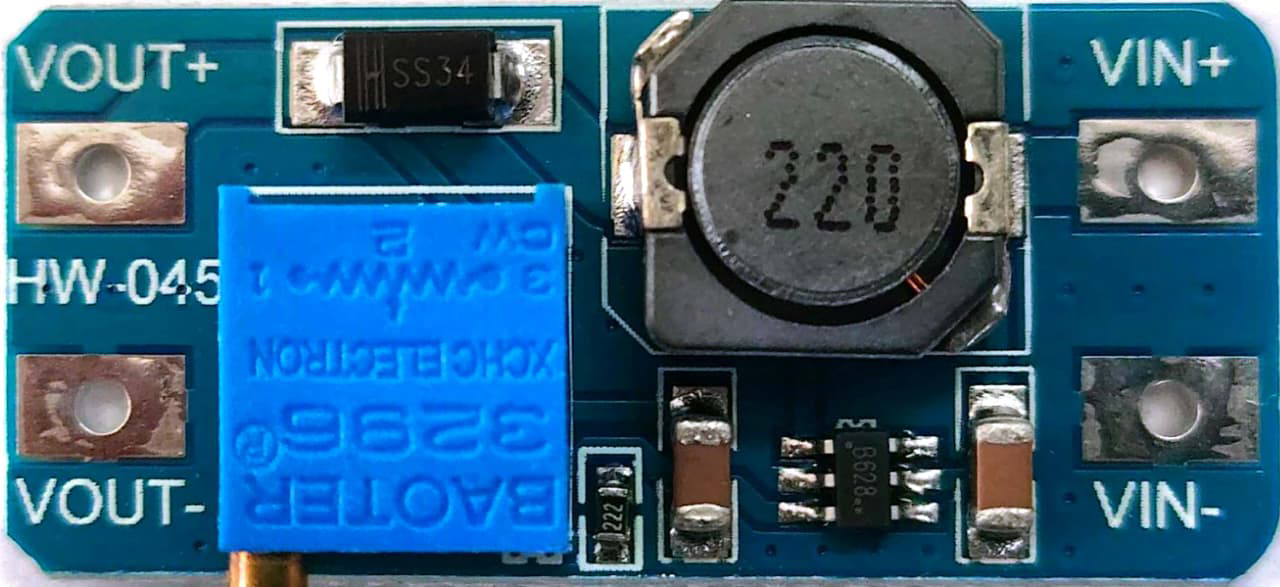
Pin Configuration and Descriptions

The MT3608 module typically has the following pinout:

Pin Name Description
VIN Input voltage (2V to 24V). Connect to the power source.
GND Ground. Connect to the negative terminal of the source.
VOUT Boosted output voltage (5V to 28V). Connect to the load.

Usage Instructions

How to Use the MT3608 in a Circuit

  1. Connect the Input Voltage:
    • Connect the VIN pin to the positive terminal of your power source (e.g., a battery).
    • Connect the GND pin to the negative terminal of the power source.
  2. Adjust the Output Voltage:
    • Use the onboard potentiometer to set the desired output voltage. Turn the potentiometer clockwise to increase the voltage and counterclockwise to decrease it.
    • Use a multimeter to measure the output voltage at the VOUT pin while adjusting.
  3. Connect the Load:
    • Connect the VOUT pin to the positive terminal of your load.
    • Connect the GND pin to the negative terminal of your load.

Important Considerations

  • Input Voltage Range: Ensure the input voltage is within the specified range (2V to 24V). Exceeding this range may damage the module.
  • Output Voltage Adjustment: Always adjust the output voltage without a load connected to avoid overvoltage damage to your components.
  • Heat Dissipation: At higher currents, the module may generate heat. Consider adding a heatsink or ensuring proper ventilation.
  • Current Limitations: The maximum output current depends on the input voltage and load. Exceeding 2A may cause instability or damage.

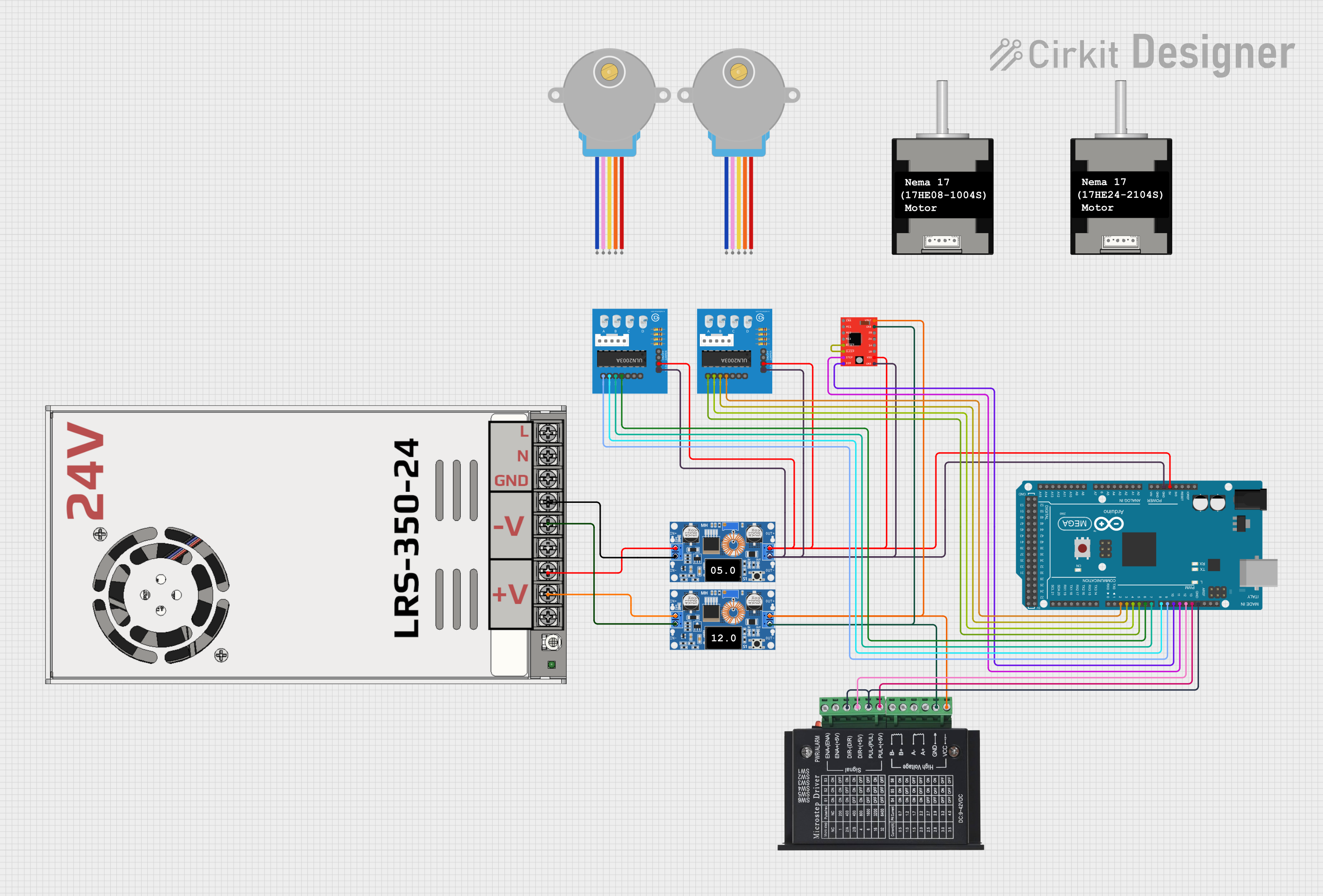
Example: Using MT3608 with Arduino UNO

The MT3608 can be used to power an Arduino UNO from a 3.7V Li-ion battery. Here's how to set it up:

  1. Connect the battery's positive terminal to the VIN pin and the negative terminal to the GND pin of the MT3608.
  2. Adjust the output voltage to 5V using the potentiometer.
  3. Connect the VOUT pin to the Arduino's 5V pin and the GND pin to the Arduino's GND pin.

Sample Code for Arduino UNO

// Example code to blink an LED using Arduino UNO powered by MT3608
// Ensure the MT3608 output is set to 5V before connecting to the Arduino

const int ledPin = 13; // Pin connected to the onboard LED

void setup() {
  pinMode(ledPin, OUTPUT); // Set the LED pin as an output
}

void loop() {
  digitalWrite(ledPin, HIGH); // Turn the LED on
  delay(1000);                // Wait for 1 second
  digitalWrite(ledPin, LOW);  // Turn the LED off
  delay(1000);                // Wait for 1 second
}

Troubleshooting and FAQs

Common Issues and Solutions

  1. No Output Voltage:

    • Check the input voltage. Ensure it is within the 2V to 24V range.
    • Verify all connections are secure and correct.
    • Ensure the potentiometer is not set to the minimum output voltage.
  2. Output Voltage is Unstable:

    • Check if the load exceeds the module's current capacity (2A max).
    • Ensure the input voltage is stable and sufficient for the desired output.
  3. Module Overheating:

    • Reduce the load current or improve ventilation.
    • Ensure the input voltage is not too close to the output voltage, as this increases current draw.
  4. Cannot Adjust Output Voltage:

    • Verify the potentiometer is functioning correctly. If damaged, replace the module.
    • Ensure no load is connected while adjusting the voltage.

FAQs

Q: Can the MT3608 be used to power a Raspberry Pi?
A: Yes, but ensure the output voltage is set to 5V and the current demand of the Raspberry Pi (including peripherals) does not exceed 2A.

Q: What happens if I exceed the input voltage range?
A: Exceeding the 24V input limit can permanently damage the module. Always use a regulated power source.

Q: Can I use the MT3608 to charge a battery?
A: No, the MT3608 is not designed for battery charging. Use a dedicated battery charging module for this purpose.