Cirkit Designer Logo
Cirkit Designer
Your all-in-one circuit design IDE
Home / 
Component Documentation

How to Use uLCD-144-G2 128: Examples, Pinouts, and Specs

Image of uLCD-144-G2 128
Cirkit Designer LogoDesign with uLCD-144-G2 128 in Cirkit Designer

Introduction

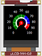
The uLCD-144-G2 128 is a compact, low-power LCD display module designed for embedded systems and microcontroller applications. It features a 128x128 pixel resolution and supports multiple communication protocols, including UART (serial). This versatile display module is capable of rendering graphics, text, and basic animations, making it ideal for projects requiring a user interface. Its small size and low power consumption make it suitable for portable and battery-powered devices.

Explore Projects Built with uLCD-144-G2 128

Use Cirkit Designer to design, explore, and prototype these projects online. Some projects support real-time simulation. Click "Open Project" to start designing instantly!
Wi-Fi Controlled RGB LED and OLED Display with ESP8266
Image of ESP thermometer reciever: A project utilizing uLCD-144-G2 128 in a practical application
This circuit features an ESP8266 microcontroller interfaced with a 128x64 OLED display via I2C for visual output and an RGB LED controlled through current-limiting resistors. The ESP8266 provides power and control signals to both the display and the LED, enabling visual feedback and status indication.
Cirkit Designer LogoOpen Project in Cirkit Designer
Arduino UNO Based Pong Game with OLED Display and Pushbutton Controls
Image of Sim test OLED Display: A project utilizing uLCD-144-G2 128 in a practical application
This circuit features an Arduino UNO microcontroller connected to an OLED 128x64 I2C Monochrome Display for visual output and two pushbuttons for user input. The Arduino runs a Pong game, with the display showing the game and the pushbuttons used to control the paddle movement. The display is interfaced via I2C (SCL and SDA), and the pushbuttons are connected to digital pins D2 and D3 for input detection.
Cirkit Designer LogoOpen Project in Cirkit Designer
Arduino UNO Controlled OLED Display with 9V Battery and Step-Down Converter
Image of digik: A project utilizing uLCD-144-G2 128 in a practical application
This circuit features an Arduino UNO connected to a 128x64 OLED display via I2C communication lines (SDA and SCL), with the Arduino providing control signals to the display. A 9V battery powers the circuit through a 12v to 5v step-down power converter, which supplies a regulated 5V to both the Arduino and the OLED display. The embedded code on the Arduino is configured to blink an onboard LED with a 1-second interval.
Cirkit Designer LogoOpen Project in Cirkit Designer
A-Star 32U4 Mini and I2C LCD Screen Battery-Powered Display
Image of lcd disolay: A project utilizing uLCD-144-G2 128 in a practical application
This circuit features an A-Star 32U4 Mini microcontroller connected to a 16x2 I2C LCD screen. The microcontroller provides power and ground to the LCD, and communicates with it via the I2C protocol using the A4 (SDA) and A5 (SCL) pins.
Cirkit Designer LogoOpen Project in Cirkit Designer

Explore Projects Built with uLCD-144-G2 128

Use Cirkit Designer to design, explore, and prototype these projects online. Some projects support real-time simulation. Click "Open Project" to start designing instantly!
Image of ESP thermometer reciever: A project utilizing uLCD-144-G2 128 in a practical application
Wi-Fi Controlled RGB LED and OLED Display with ESP8266
This circuit features an ESP8266 microcontroller interfaced with a 128x64 OLED display via I2C for visual output and an RGB LED controlled through current-limiting resistors. The ESP8266 provides power and control signals to both the display and the LED, enabling visual feedback and status indication.
Cirkit Designer LogoOpen Project in Cirkit Designer
Image of Sim test OLED Display: A project utilizing uLCD-144-G2 128 in a practical application
Arduino UNO Based Pong Game with OLED Display and Pushbutton Controls
This circuit features an Arduino UNO microcontroller connected to an OLED 128x64 I2C Monochrome Display for visual output and two pushbuttons for user input. The Arduino runs a Pong game, with the display showing the game and the pushbuttons used to control the paddle movement. The display is interfaced via I2C (SCL and SDA), and the pushbuttons are connected to digital pins D2 and D3 for input detection.
Cirkit Designer LogoOpen Project in Cirkit Designer
Image of digik: A project utilizing uLCD-144-G2 128 in a practical application
Arduino UNO Controlled OLED Display with 9V Battery and Step-Down Converter
This circuit features an Arduino UNO connected to a 128x64 OLED display via I2C communication lines (SDA and SCL), with the Arduino providing control signals to the display. A 9V battery powers the circuit through a 12v to 5v step-down power converter, which supplies a regulated 5V to both the Arduino and the OLED display. The embedded code on the Arduino is configured to blink an onboard LED with a 1-second interval.
Cirkit Designer LogoOpen Project in Cirkit Designer
Image of lcd disolay: A project utilizing uLCD-144-G2 128 in a practical application
A-Star 32U4 Mini and I2C LCD Screen Battery-Powered Display
This circuit features an A-Star 32U4 Mini microcontroller connected to a 16x2 I2C LCD screen. The microcontroller provides power and ground to the LCD, and communicates with it via the I2C protocol using the A4 (SDA) and A5 (SCL) pins.
Cirkit Designer LogoOpen Project in Cirkit Designer

Common Applications

  • User interfaces for embedded systems
  • Portable devices and wearables
  • Industrial control panels
  • IoT devices with visual feedback
  • Educational and hobbyist projects

Technical Specifications

Below are the key technical details of the uLCD-144-G2 128:

Parameter Value
Display Resolution 128x128 pixels
Display Type TFT LCD
Communication Protocol UART (Serial)
Operating Voltage 4.0V to 5.5V
Typical Current Consumption ~12mA (at 5V)
Backlight Control PWM adjustable
Dimensions 44.1mm x 47.6mm x 5.6mm
Operating Temperature -10°C to +60°C

Pin Configuration

The uLCD-144-G2 128 has a 5-pin interface for communication and power. Below is the pinout:

Pin Name Description
1 GND Ground connection
2 VCC Power supply (4.0V to 5.5V)
3 TX UART Transmit (data sent from the display)
4 RX UART Receive (data sent to the display)
5 RESET Active-low reset pin to restart the display module

Usage Instructions

Connecting the uLCD-144-G2 128 to a Microcontroller

To use the uLCD-144-G2 128, connect it to a microcontroller (e.g., Arduino UNO) as follows:

  1. Connect the GND pin of the display to the GND pin of the microcontroller.
  2. Connect the VCC pin of the display to the 5V pin of the microcontroller.
  3. Connect the TX pin of the display to the RX pin of the microcontroller.
  4. Connect the RX pin of the display to the TX pin of the microcontroller.
  5. Optionally, connect the RESET pin to a GPIO pin on the microcontroller for manual resets.

Example Code for Arduino UNO

Below is an example Arduino sketch to display text on the uLCD-144-G2 128:

#include <SoftwareSerial.h>

// Define the RX and TX pins for SoftwareSerial
SoftwareSerial lcdSerial(10, 11); // RX = pin 10, TX = pin 11

void setup() {
  lcdSerial.begin(9600); // Initialize serial communication with the display
  delay(1000); // Allow the display to initialize

  // Clear the screen and set background color
  lcdSerial.write(0xFF); // Command prefix
  lcdSerial.write(0xD7); // Clear screen command
  lcdSerial.write(0x00); // Background color (black)

  // Display text on the screen
  lcdSerial.write(0xFF); // Command prefix
  lcdSerial.write(0xE4); // Text command
  lcdSerial.write(0x01); // Font size (1 = small)
  lcdSerial.write(0x00); // X-coordinate (0)
  lcdSerial.write(0x00); // Y-coordinate (0)
  lcdSerial.print("Hello, World!"); // Text to display
}

void loop() {
  // No actions in the loop
}

Important Considerations

  • Ensure the display's operating voltage matches the microcontroller's logic level (5V for Arduino UNO).
  • Use a level shifter if connecting to a 3.3V microcontroller.
  • Avoid sending commands to the display too quickly; allow sufficient delays between commands.
  • Refer to the manufacturer's command set documentation for advanced features like graphics and animations.

Troubleshooting and FAQs

Common Issues

  1. The display does not turn on:

    • Verify the power connections (VCC and GND).
    • Ensure the power supply provides sufficient voltage (4.0V to 5.5V).
  2. No text or graphics appear on the screen:

    • Check the TX and RX connections between the microcontroller and the display.
    • Ensure the baud rate in the code matches the display's default baud rate (9600 bps).
  3. The display resets unexpectedly:

    • Verify that the power supply is stable and not dropping below 4.0V.
    • Check for loose connections, especially on the RESET pin.
  4. Text or graphics appear distorted:

    • Ensure the correct command sequence is being sent to the display.
    • Verify that the display's resolution (128x128) is being respected in the code.

Tips for Troubleshooting

  • Use a logic analyzer or oscilloscope to monitor the UART communication.
  • Test the display with a simple "Hello, World!" program to confirm basic functionality.
  • Consult the manufacturer's datasheet for detailed command descriptions and examples.

By following this documentation, you can effectively integrate the uLCD-144-G2 128 into your projects and troubleshoot common issues.