How to Use KY-022: Examples, Pinouts, and Specs
Introduction
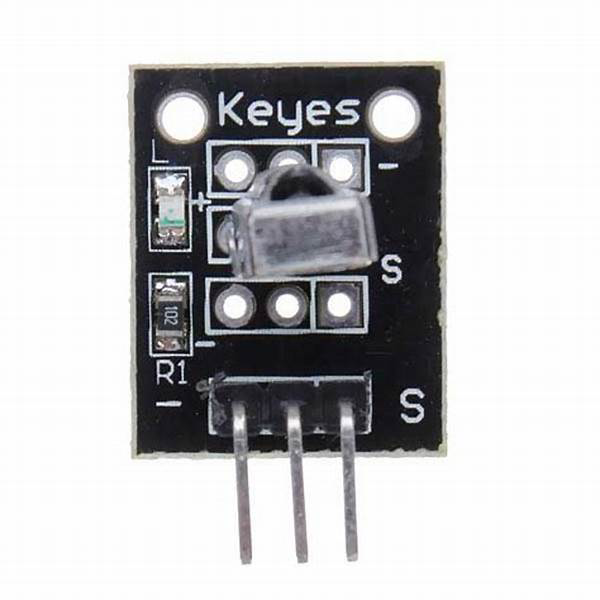
The KY-022 is an infrared (IR) receiver module designed to receive IR signals from remote controls. It operates at a wavelength of 940 nm and is widely used in applications such as remote control systems, IR communication, and home automation. The module is compact, easy to use, and compatible with microcontrollers like Arduino, making it a popular choice for hobbyists and professionals alike.
Explore Projects Built with KY-022


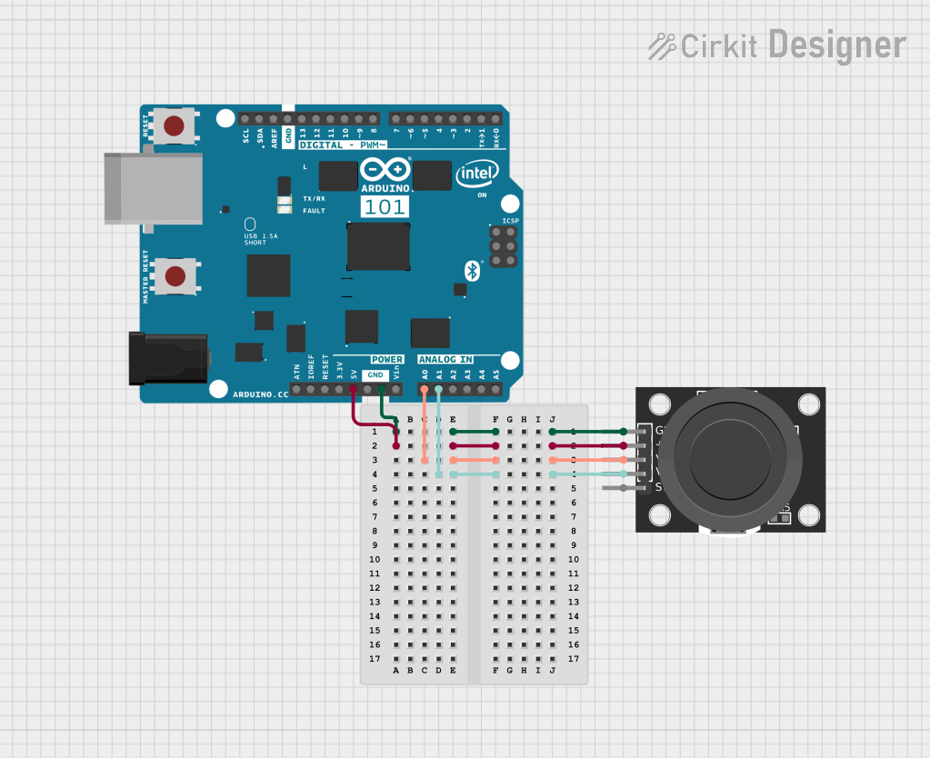
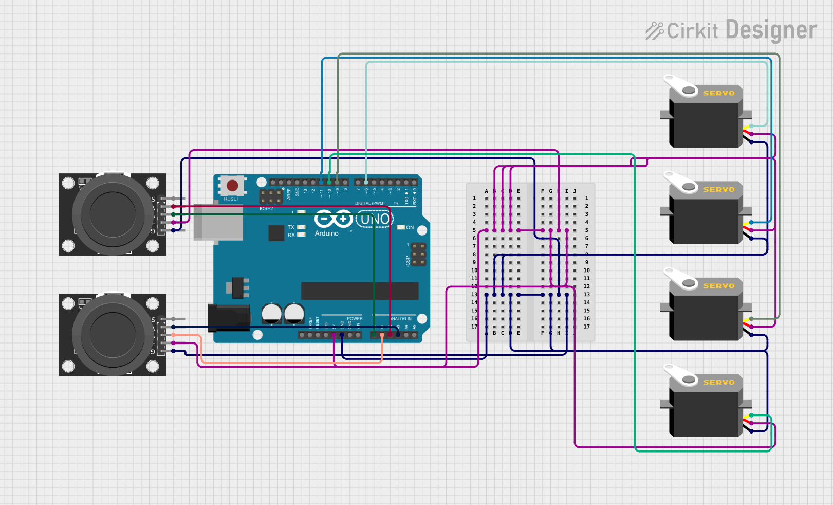
Explore Projects Built with KY-022
Common Applications:
- Remote control systems for TVs, air conditioners, and other appliances
- IR communication between devices
- Home automation projects
- Robotics and IoT systems requiring IR signal reception
Technical Specifications
Below are the key technical details of the KY-022 module:
| Parameter | Value |
|---|---|
| Operating Voltage | 3.3V to 5V |
| Operating Current | 0.4 mA to 1.5 mA |
| Carrier Frequency | 38 kHz |
| Wavelength | 940 nm |
| Reception Distance | Up to 18 meters (line of sight) |
| Output Signal | Digital (active low) |
| Dimensions | 30mm x 15mm x 10mm |
Pin Configuration:
The KY-022 module has three pins, as described in the table below:
| Pin | Name | Description |
|---|---|---|
| 1 | Signal | Digital output pin for the received IR signal |
| 2 | VCC | Power supply pin (3.3V to 5V) |
| 3 | GND | Ground pin |
Usage Instructions
How to Use the KY-022 in a Circuit
Connect the Pins:
- Connect the
VCCpin to a 3.3V or 5V power supply. - Connect the
GNDpin to the ground of your circuit. - Connect the
Signalpin to a digital input pin on your microcontroller (e.g., Arduino).
- Connect the
Place the Module:
- Ensure the KY-022 is positioned to face the IR transmitter (e.g., a remote control) for optimal signal reception.
Load the Code:
- If using an Arduino, you can use the
IRremotelibrary to decode the received IR signals.
- If using an Arduino, you can use the
Example Arduino Code
Below is an example of how to use the KY-022 with an Arduino UNO to decode IR signals:
#include <IRremote.h> // Include the IRremote library

const int RECV_PIN = 2; // Define the pin connected to the KY-022 Signal pin
IRrecv irrecv(RECV_PIN); // Create an IR receiver object
decode_results results;  // Create a variable to store decoded results

void setup() {
  Serial.begin(9600); // Initialize serial communication at 9600 baud
  irrecv.enableIRIn(); // Start the IR receiver
  Serial.println("IR Receiver is ready to decode signals.");
}

void loop() {
  if (irrecv.decode(&results)) { // Check if a signal is received
    Serial.print("Received IR code: ");
    Serial.println(results.value, HEX); // Print the received code in HEX format
    irrecv.resume(); // Prepare to receive the next signal
  }
}
Important Considerations:
- Power Supply: Ensure the module is powered within its operating voltage range (3.3V to 5V).
- Line of Sight: The module requires a clear line of sight to the IR transmitter for reliable operation.
- Ambient Light: Avoid using the module in environments with excessive IR interference (e.g., direct sunlight).
Troubleshooting and FAQs
Common Issues and Solutions:
No Signal Detected:
- Ensure the IR transmitter (e.g., remote control) is functional and emitting signals.
- Verify the connections to the KY-022 module, especially the
Signalpin. - Check that the module is powered correctly (3.3V to 5V).
Unstable or Incorrect Readings:
- Ensure the module is not exposed to strong ambient IR sources, such as sunlight or fluorescent lights.
- Verify that the IR transmitter is within the module's reception range (up to 18 meters).
Arduino Code Not Working:
- Confirm that the
IRremotelibrary is installed in your Arduino IDE. - Double-check the pin number defined in the code matches the Arduino pin connected to the KY-022
Signalpin.
- Confirm that the
FAQs:
Q: Can the KY-022 receive signals from any remote control?
A: The KY-022 is compatible with most remote controls that operate at a carrier frequency of 38 kHz, which is standard for many consumer devices.
Q: Can I use the KY-022 with a Raspberry Pi?
A: Yes, the KY-022 can be used with a Raspberry Pi. However, you will need to use appropriate libraries (e.g., lirc) and configure the GPIO pins for IR signal reception.
Q: What is the maximum range of the KY-022?
A: The KY-022 can receive IR signals from up to 18 meters away, provided there is a clear line of sight and minimal interference.
Q: How do I test if the KY-022 is working?
A: You can use an Arduino with the provided example code to check if the module is receiving IR signals. Alternatively, you can use a multimeter to monitor the Signal pin for changes when an IR signal is transmitted.
By following this documentation, you should be able to effectively use the KY-022 IR receiver module in your projects!