How to Use xt90e: Examples, Pinouts, and Specs
Introduction
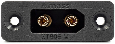
The XT90E is a high-current connector designed for use in RC (radio-controlled) applications, such as drones, electric vehicles, and high-power battery systems. It features a secure locking mechanism and a robust design, making it ideal for applications requiring reliable and safe power delivery. With the ability to handle up to 90A of continuous current, the XT90E is a popular choice for hobbyists and professionals alike.
Explore Projects Built with xt90e


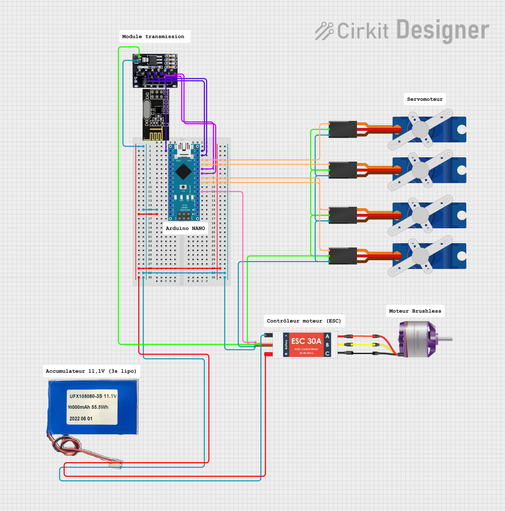
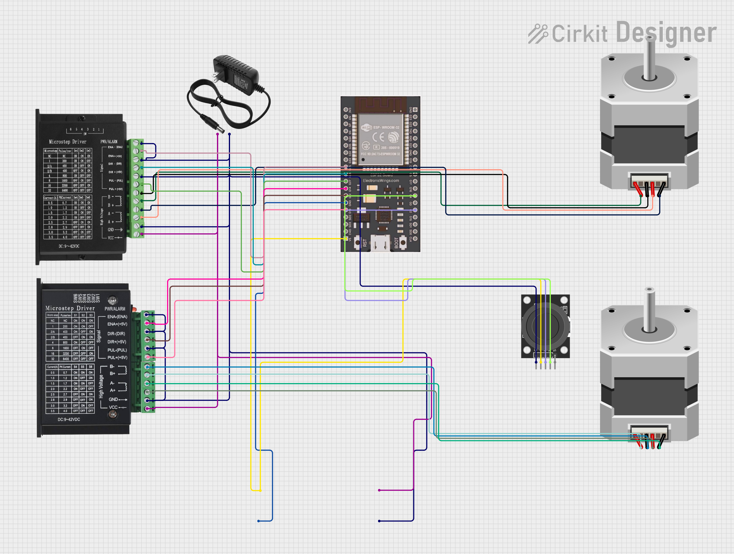
Explore Projects Built with xt90e
Common Applications and Use Cases
- RC vehicles (cars, boats, drones, and planes)
- High-power battery packs
- Electric bikes and scooters
- Power distribution systems in DIY electronics
- Industrial equipment requiring high-current connections
Technical Specifications
The XT90E connector is designed to provide a reliable and efficient connection for high-current applications. Below are its key technical details:
| Parameter | Specification |
|---|---|
| Rated Current | 90A (continuous) |
| Peak Current | 120A (for short durations) |
| Voltage Rating | Up to 500V DC |
| Contact Resistance | ≤ 0.6 mΩ |
| Operating Temperature | -20°C to 120°C |
| Material (Housing) | Nylon (flame-retardant) |
| Material (Contacts) | Gold-plated copper |
| Connector Type | Male and Female (pair) |
| Mounting Style | Panel-mount (XT90E variant) |
Pin Configuration and Descriptions
The XT90E connector consists of two main pins for power delivery. Below is the pin configuration:
| Pin | Description | Notes |
|---|---|---|
| Pin 1 | Positive (+) Terminal | Connects to the positive side of the power source |
| Pin 2 | Negative (-) Terminal | Connects to the negative side of the power source |
Usage Instructions
How to Use the XT90E in a Circuit
- Prepare the Wires: Strip the insulation from the wires you intend to connect to the XT90E. Ensure the wire gauge is appropriate for the current rating (e.g., 10-12 AWG for 90A).
- Solder the Wires:
- Heat the soldering iron to the appropriate temperature (around 350°C for most solder types).
- Tin the wire ends and the XT90E connector terminals with solder.
- Insert the tinned wire into the connector terminal and apply heat until the solder flows and creates a secure connection.
- Assemble the Connector: Once the wires are soldered, assemble the XT90E housing by snapping the male and female parts together. Ensure the locking mechanism is engaged for a secure connection.
- Panel Mounting: For the XT90E variant, mount the connector to a panel or enclosure using the provided screws and mounting holes.
Important Considerations and Best Practices
- Wire Gauge: Use wires with a gauge suitable for the current rating to prevent overheating or voltage drops.
- Soldering: Ensure proper soldering techniques to avoid cold joints, which can lead to poor connections or overheating.
- Polarity: Double-check the polarity of the connections to prevent damage to your circuit or components.
- Secure Mounting: When using the panel-mount version, ensure the connector is securely fastened to prevent movement or stress on the wires.
- Avoid Overcurrent: Do not exceed the rated current (90A continuous) to prevent overheating or damage to the connector.
Example: Connecting XT90E to an Arduino UNO Power Supply
While the XT90E is not directly used with low-power devices like the Arduino UNO, it can be part of a power distribution system. For example, you can use the XT90E to connect a high-capacity battery to a voltage regulator, which then powers the Arduino UNO.
// Example: Using an XT90E-connected battery to power an Arduino UNO
// Ensure the battery voltage is regulated to 5V before connecting to the Arduino

void setup() {
  // Initialize the Arduino
  pinMode(LED_BUILTIN, OUTPUT); // Set built-in LED pin as output
}

void loop() {
  // Blink the built-in LED to indicate power is supplied
  digitalWrite(LED_BUILTIN, HIGH); // Turn the LED on
  delay(1000);                     // Wait for 1 second
  digitalWrite(LED_BUILTIN, LOW);  // Turn the LED off
  delay(1000);                     // Wait for 1 second
}
Troubleshooting and FAQs
Common Issues and Solutions
Loose Connection:
- Issue: The connector feels loose or disconnects easily.
- Solution: Ensure the locking mechanism is fully engaged. Check for wear or damage to the housing.
Overheating:
- Issue: The connector becomes hot during operation.
- Solution: Verify that the current does not exceed the rated 90A. Check for proper soldering and ensure the wire gauge is appropriate.
Polarity Reversal:
- Issue: The circuit does not work, or components are damaged.
- Solution: Double-check the polarity of the connections before powering the circuit.
Difficulty in Soldering:
- Issue: Solder does not adhere to the connector terminals.
- Solution: Clean the terminals and use flux to improve solder flow. Ensure the soldering iron is at the correct temperature.
FAQs
Q: Can the XT90E handle AC power?
- A: The XT90E is primarily designed for DC power applications. While it can technically handle AC, it is not recommended due to potential safety concerns.
Q: Is the XT90E waterproof?
- A: No, the XT90E is not waterproof. If used in outdoor or wet environments, additional waterproofing measures are required.
Q: Can I use the XT90E for currents above 90A?
- A: The XT90E can handle up to 120A for short durations, but continuous operation above 90A is not recommended as it may cause overheating or damage.
Q: How do I disconnect the XT90E?
- A: Press the locking tabs on the connector housing and gently pull the male and female parts apart.
By following this documentation, you can effectively use the XT90E connector in your high-current applications while ensuring safety and reliability.