
How to Use 1.27 inch 16-bit Color OLED w microSD holder: Examples, Pinouts, and Specs
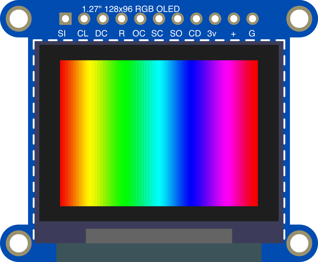
 Design with 1.27 inch 16-bit Color OLED w microSD holder in Cirkit Designer
Introduction
The Adafruit 1.27 inch 16-bit Color OLED w microSD Holder (Part ID: 1673) is a compact and versatile display module designed for high-quality graphical output. Featuring a 1.27-inch diagonal OLED screen, this module supports 16-bit color graphics, providing vibrant and sharp visuals. Additionally, it includes an integrated microSD card holder, enabling convenient storage and retrieval of data such as images, fonts, or other resources for display.
This module is ideal for applications requiring a small, high-resolution display, such as:
- Wearable devices
- Portable electronics
- IoT dashboards
- Embedded systems with graphical interfaces
- Prototyping and hobbyist projects
Explore Projects Built with 1.27 inch 16-bit Color OLED w microSD holder
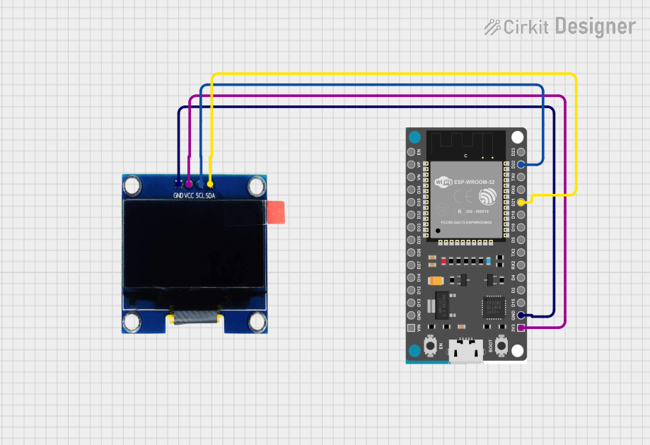 Open Project in Cirkit Designer
 Open Project in Cirkit Designer
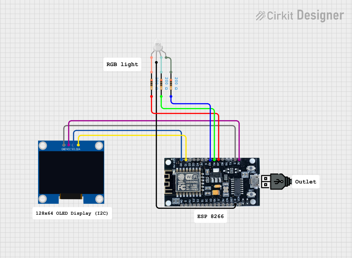 Open Project in Cirkit Designer
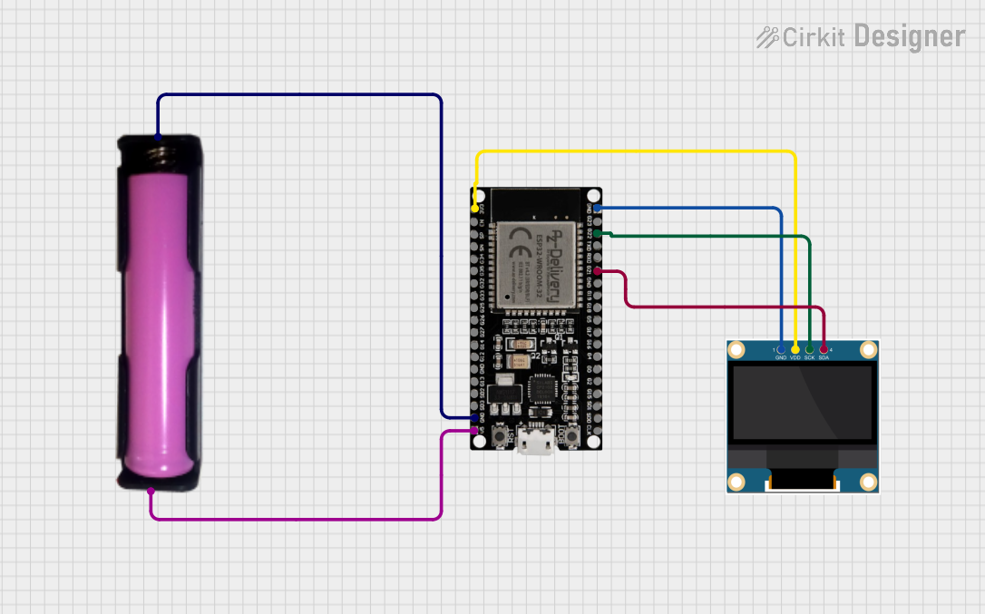 Open Project in Cirkit Designer
Explore Projects Built with 1.27 inch 16-bit Color OLED w microSD holder
Open Project in Cirkit DesignerOpen Project in Cirkit DesignerOpen Project in Cirkit DesignerOpen Project in Cirkit DesignerTechnical Specifications
Key Specifications
| Parameter | Value |
|---|---|
| Display Type | OLED |
| Screen Size | 1.27 inches (diagonal) |
| Resolution | 128 x 96 pixels |
| Color Depth | 16-bit (65,536 colors) |
| Interface | SPI |
| Operating Voltage | 3.3V to 5V |
| Current Consumption | ~25mA (typical) |
| microSD Card Support | Yes |
| Dimensions | 35.5mm x 30.5mm x 5mm |
Pin Configuration
The module has a total of 7 pins for interfacing. Below is the pinout description:
| Pin Name | Description |
|---|---|
| GND | Ground connection |
| VIN | Power input (3.3V to 5V) |
| 3V3 | 3.3V output (can be used to power other components) |
| CLK | SPI Clock (SCK) |
| MOSI | SPI Master Out Slave In (data input to the OLED) |
| CS | Chip Select (active low, used to select the OLED display) |
| RST | Reset (active low, used to reset the display) |
| DC | Data/Command (used to differentiate between data and command instructions) |
Usage Instructions
Connecting the OLED to an Arduino UNO
To use the Adafruit 1.27 inch OLED with an Arduino UNO, follow these steps:
Wiring: Connect the OLED module to the Arduino as shown below:
OLED Pin Arduino Pin GND GND VIN 5V CLK D13 MOSI D11 CS D10 RST D9 DC D8 Install Libraries:
- Download and install the Adafruit GFX library and the Adafruit SSD1351 library from the Arduino Library Manager.
Example Code: Use the following example code to display a simple graphic on the OLED:
// Include necessary libraries
#include <Adafruit_GFX.h>       // Core graphics library
#include <Adafruit_SSD1351.h>  // OLED driver library
#include <SPI.h>               // SPI communication library

// Define OLED pins
#define OLED_CS   10  // Chip Select pin
#define OLED_RST  9   // Reset pin
#define OLED_DC   8   // Data/Command pin

// Create an instance of the display
Adafruit_SSD1351 display = Adafruit_SSD1351(128, 96, &SPI, OLED_CS, OLED_DC, OLED_RST);

void setup() {
  // Initialize the display
  display.begin();
  display.fillScreen(SSD1351_BLACK);  // Clear the screen with black color

  // Draw a red rectangle
  display.fillRect(10, 10, 50, 30, SSD1351_RED);

  // Display text
  display.setTextColor(SSD1351_WHITE);  // Set text color to white
  display.setCursor(10, 50);            // Set text position
  display.print("Hello, OLED!");        // Print text to the screen
}

void loop() {
  // Nothing to do here
}
Important Considerations
- Power Supply: Ensure the module is powered within the specified voltage range (3.3V to 5V). Exceeding this range may damage the OLED.
- SPI Communication: The module uses SPI for communication. Ensure no other SPI devices on the same bus conflict with the OLED's settings.
- microSD Card: If using the microSD card holder, format the card as FAT16 or FAT32 for compatibility. Use libraries like
SD.hto access files on the card.
Troubleshooting and FAQs
Common Issues
The display does not turn on:
- Verify all connections are secure and match the pinout table.
- Ensure the power supply voltage is within the specified range.
- Check if the
display.begin()function is called in the setup.
Graphics are distorted or not displayed correctly:
- Ensure the correct libraries (Adafruit GFX and SSD1351) are installed and up to date.
- Verify the SPI connections and pin definitions in the code.
microSD card is not detected:
- Ensure the card is formatted as FAT16 or FAT32.
- Check the wiring and ensure the card is properly inserted into the holder.
Tips for Troubleshooting
- Use a multimeter to check for continuity and proper voltage levels on the pins.
- Test the module with example sketches provided in the Adafruit SSD1351 library to rule out software issues.
- If using multiple SPI devices, ensure each device has a unique Chip Select (CS) pin.
By following this documentation, you can effectively integrate and utilize the Adafruit 1.27 inch 16-bit Color OLED w microSD Holder in your projects.