How to Use GX16 8pin: Examples, Pinouts, and Specs
Introduction
The GX16 8pin connector, manufactured by Base (Part ID: GX16 8pin), is a circular connector designed for secure and reliable electrical connections. It features 8 pins, making it suitable for transmitting multiple signals or power lines in a compact form factor. Its robust metal construction ensures durability, while its threaded locking mechanism provides a secure connection, even in environments subject to vibration or movement.
Explore Projects Built with GX16 8pin


Explore Projects Built with GX16 8pin
Common Applications
- Audio Equipment: Used for connecting microphones, speakers, and other audio devices.
- Industrial Equipment: Ideal for machinery requiring multiple signal or power connections.
- Lighting Systems: Commonly used in stage lighting and other multi-channel lighting setups.
- Robotics: Facilitates connections between control systems and actuators or sensors.
Technical Specifications
Key Technical Details
| Parameter | Specification |
|---|---|
| Manufacturer | Base |
| Part ID | GX16 8pin |
| Number of Pins | 8 |
| Connector Type | Circular |
| Contact Material | Copper Alloy |
| Shell Material | Nickel-Plated Brass |
| Rated Voltage | 250V AC/DC |
| Rated Current | 5A per pin |
| Operating Temperature | -20°C to +85°C |
| Mounting Style | Panel Mount or Cable Mount |
| Locking Mechanism | Threaded Coupling |
Pin Configuration and Descriptions
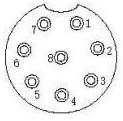
The GX16 8pin connector has 8 pins arranged in a circular pattern. Below is the pinout configuration:
| Pin Number | Description | Typical Use Case |
|---|---|---|
| 1 | Signal/Power Line 1 | Data or power transmission |
| 2 | Signal/Power Line 2 | Data or power transmission |
| 3 | Signal/Power Line 3 | Data or power transmission |
| 4 | Signal/Power Line 4 | Data or power transmission |
| 5 | Signal/Power Line 5 | Data or power transmission |
| 6 | Signal/Power Line 6 | Data or power transmission |
| 7 | Signal/Power Line 7 | Data or power transmission |
| 8 | Signal/Power Line 8 | Data or power transmission |
Usage Instructions
How to Use the GX16 8pin Connector in a Circuit
Wiring the Connector:
- Identify the pin numbers on the connector (usually marked on the connector itself).
- Solder the wires to the corresponding pins. Ensure proper insulation to avoid short circuits.
- For panel-mount connectors, secure the connector to the panel using the provided nut.
Connecting the Mating Parts:
- Align the male and female connectors using the alignment notch.
- Screw the threaded coupling to secure the connection.
Testing the Connection:
- Use a multimeter to verify continuity between the pins of the connected parts.
- Ensure there are no short circuits between adjacent pins.
Important Considerations and Best Practices
- Avoid Overloading: Do not exceed the rated voltage (250V) or current (5A per pin) to prevent overheating or damage.
- Proper Soldering: Use a soldering iron with a fine tip for precise soldering. Avoid excessive solder, which may cause shorts.
- Environmental Protection: If used in outdoor or harsh environments, consider using a waterproof version or additional sealing.
- Cable Strain Relief: Use strain relief clamps to prevent stress on the soldered connections.
Example: Connecting to an Arduino UNO
The GX16 8pin connector can be used to interface multiple sensors or actuators with an Arduino UNO. Below is an example of wiring and code for reading data from 8 sensors connected via the GX16 8pin connector.
Wiring
- Connect each sensor's output to one of the 8 pins on the GX16 connector.
- Connect the corresponding pins on the mating connector to the Arduino's digital or analog input pins.
Arduino Code
// Example code for reading 8 sensors connected via GX16 8pin connector
// Ensure proper wiring between the GX16 pins and Arduino input pins

// Define the Arduino pins connected to the GX16 connector
const int sensorPins[8] = {A0, A1, A2, A3, A4, A5, 2, 3}; // Analog and digital pins

void setup() {
  Serial.begin(9600); // Initialize serial communication
  for (int i = 0; i < 8; i++) {
    pinMode(sensorPins[i], INPUT); // Set all pins as input
  }
}

void loop() {
  Serial.println("Sensor Readings:");
  for (int i = 0; i < 8; i++) {
    int sensorValue = analogRead(sensorPins[i]); // Read sensor value
    Serial.print("Sensor ");
    Serial.print(i + 1);
    Serial.print(": ");
    Serial.println(sensorValue); // Print sensor value
  }
  delay(1000); // Wait 1 second before the next reading
}
Troubleshooting and FAQs
Common Issues and Solutions
| Issue | Possible Cause | Solution |
|---|---|---|
| No connection between pins | Poor soldering or loose connection | Re-solder the pins and check alignment |
| Short circuit between pins | Excess solder or damaged insulation | Remove excess solder and re-insulate |
| Connector does not lock properly | Misalignment of male and female parts | Align the connectors and tighten the thread |
| Signal interference or noise | Poor shielding or grounding | Use shielded cables and ensure proper grounding |
FAQs
Can the GX16 8pin connector handle high-frequency signals?
- Yes, but for very high-frequency signals, ensure proper shielding to minimize interference.
Is the GX16 8pin connector waterproof?
- The standard version is not waterproof. However, waterproof variants are available for outdoor use.
Can I use the GX16 8pin connector for power transmission?
- Yes, as long as the current does not exceed 5A per pin and the voltage is within 250V.
How do I clean the connector?
- Use a soft brush or compressed air to remove dust. Avoid using water or harsh chemicals.
By following this documentation, users can effectively integrate the GX16 8pin connector into their projects and troubleshoot common issues with ease.