How to Use esp32 breakout board: Examples, Pinouts, and Specs
Introduction
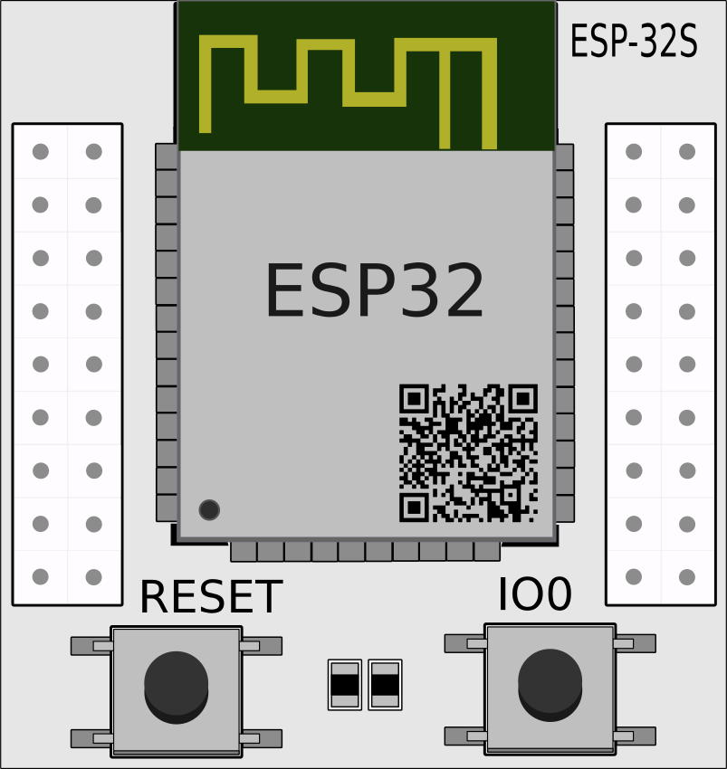
The ESP32 Breakout Board is a development board featuring the ESP32 microcontroller, a powerful and versatile chip with built-in Wi-Fi and Bluetooth capabilities. This board is designed to simplify prototyping and development for Internet of Things (IoT) applications, wireless communication projects, and smart devices. Its compact design and rich feature set make it a popular choice for hobbyists, engineers, and developers.
Explore Projects Built with esp32 breakout board


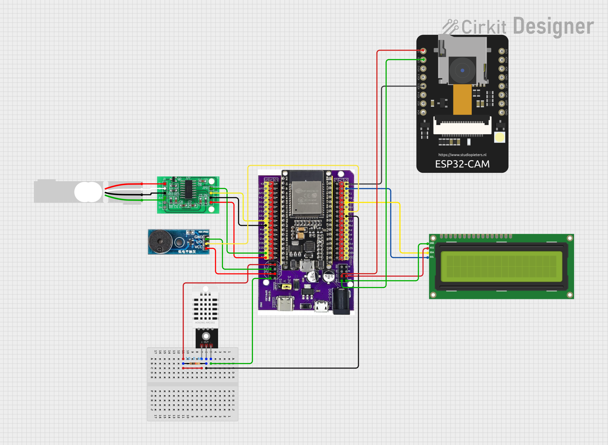
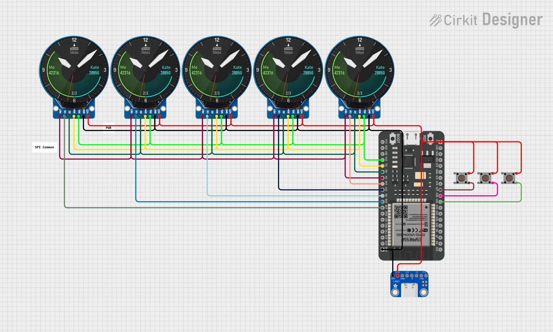
Explore Projects Built with esp32 breakout board
Common Applications and Use Cases
- IoT devices and smart home automation
- Wireless sensor networks
- Bluetooth-enabled devices
- Real-time data monitoring and logging
- Robotics and automation systems
- Prototyping for Wi-Fi and Bluetooth applications
Technical Specifications
Key Technical Details
- Microcontroller: ESP32 dual-core processor
- Clock Speed: Up to 240 MHz
- Flash Memory: Typically 4 MB (varies by model)
- SRAM: 520 KB
- Connectivity: Wi-Fi (802.11 b/g/n), Bluetooth 4.2 (Classic and BLE)
- Operating Voltage: 3.3V
- Input Voltage: 5V (via USB) or 3.3V (via pin)
- GPIO Pins: 30+ (varies by breakout board model)
- ADC Channels: Up to 18 (12-bit resolution)
- DAC Channels: 2 (8-bit resolution)
- PWM Outputs: Multiple (configurable on GPIO pins)
- Communication Protocols: UART, SPI, I2C, I2S, CAN, and more
- Power Consumption: Ultra-low power modes available
- Dimensions: Varies by breakout board, typically compact
Pin Configuration and Descriptions
Below is a typical pinout for an ESP32 breakout board. Note that the exact pin configuration may vary depending on the specific model.
| Pin | Name | Description |
|---|---|---|
| 1 | 3V3 | 3.3V power output |
| 2 | GND | Ground |
| 3 | EN | Enable pin (active high, used to reset the chip) |
| 4 | GPIO0 | General-purpose I/O, also used for boot mode selection |
| 5 | GPIO2 | General-purpose I/O, often used for onboard LED |
| 6 | GPIO12-39 | General-purpose I/O pins with various functions (ADC, PWM, UART, etc.) |
| 7 | TX0/RX0 | UART0 communication pins (default serial communication) |
| 8 | VIN | Input voltage (5V when powered via USB) |
| 9 | ADC1/ADC2 | Analog-to-digital converter channels |
| 10 | DAC1/DAC2 | Digital-to-analog converter channels |
| 11 | I2C (SDA/SCL) | I2C communication pins (configurable) |
| 12 | SPI (MOSI/MISO/SCK/CS) | SPI communication pins (configurable) |
Usage Instructions
How to Use the ESP32 Breakout Board in a Circuit
Powering the Board:
- Connect the board to a computer or USB power source using a micro-USB cable.
- Alternatively, supply 3.3V to the 3V3 pin or 5V to the VIN pin.
Programming the ESP32:
- Install the Arduino IDE and add the ESP32 board support package.
- Select the appropriate ESP32 board model from the Tools menu.
- Connect the board to your computer and upload your code.
Connecting Peripherals:
- Use the GPIO pins to connect sensors, actuators, or other peripherals.
- Ensure that the voltage levels of connected devices are compatible with the ESP32 (3.3V logic).
Wi-Fi and Bluetooth Setup:
- Use the built-in libraries (e.g.,
WiFi.handBluetoothSerial.h) to configure wireless communication.
- Use the built-in libraries (e.g.,
Important Considerations and Best Practices
- Voltage Levels: The ESP32 operates at 3.3V logic. Avoid connecting 5V signals directly to GPIO pins.
- Boot Mode: Ensure GPIO0 is pulled low during boot to enter programming mode.
- Power Supply: Use a stable power source to avoid unexpected resets or instability.
- Heat Management: The ESP32 can get warm during operation. Ensure proper ventilation if used in enclosed spaces.
Example Code for Arduino UNO Integration
Below is an example of using the ESP32 to connect to a Wi-Fi network and send data to a server:
#include <WiFi.h> // Include the Wi-Fi library

// Replace with your network credentials
const char* ssid = "Your_SSID";
const char* password = "Your_PASSWORD";

void setup() {
  Serial.begin(115200); // Initialize serial communication
  delay(1000);

  // Connect to Wi-Fi
  Serial.print("Connecting to Wi-Fi");
  WiFi.begin(ssid, password);
  while (WiFi.status() != WL_CONNECTED) {
    delay(500);
    Serial.print(".");
  }
  Serial.println("\nWi-Fi connected!");
  Serial.print("IP Address: ");
  Serial.println(WiFi.localIP()); // Print the assigned IP address
}

void loop() {
  // Add your main code here
}
Troubleshooting and FAQs
Common Issues and Solutions
ESP32 Not Detected by Computer:
- Ensure the correct USB driver is installed (e.g., CP210x or CH340 driver).
- Check the USB cable for data transfer capability (some cables are power-only).
Upload Fails with Timeout Error:
- Hold the BOOT button on the ESP32 while uploading the code.
- Verify the correct board and COM port are selected in the Arduino IDE.
Wi-Fi Connection Fails:
- Double-check the SSID and password.
- Ensure the router is within range and supports 2.4 GHz (ESP32 does not support 5 GHz).
Random Resets or Instability:
- Use a stable power source with sufficient current (at least 500 mA).
- Avoid excessive power draw from GPIO pins.
FAQs
Q: Can the ESP32 operate on battery power?
A: Yes, the ESP32 can be powered by a LiPo battery or other 3.3V/5V sources. Use a voltage regulator if needed.Q: How do I use the ESP32's Bluetooth functionality?
A: Use theBluetoothSeriallibrary for Bluetooth Classic or theBLElibrary for BLE applications.Q: Can I use the ESP32 with other IDEs?
A: Yes, the ESP32 is compatible with other IDEs like PlatformIO and Espressif's own ESP-IDF.Q: What is the maximum range of the ESP32's Wi-Fi?
A: The range depends on environmental factors but typically extends up to 100 meters in open spaces.
This documentation provides a comprehensive guide to using the ESP32 Breakout Board effectively. Happy prototyping!