
How to Use 12V PWM 80x80mm Fan: Examples, Pinouts, and Specs
 Design with 12V PWM 80x80mm Fan in Cirkit Designer
Introduction
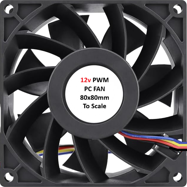
The 12V PWM 80x80mm fan is a compact and efficient cooling solution designed for a variety of applications. Its 80x80mm size makes it ideal for use in small enclosures, such as computer cases, power supplies, and other electronic devices. The fan features a 4-pin connector, enabling pulse-width modulation (PWM) control for variable speed operation. This allows users to optimize airflow and reduce noise levels based on system requirements.
Explore Projects Built with 12V PWM 80x80mm Fan
 Open Project in Cirkit Designer
 Open Project in Cirkit Designer
 Open Project in Cirkit Designer
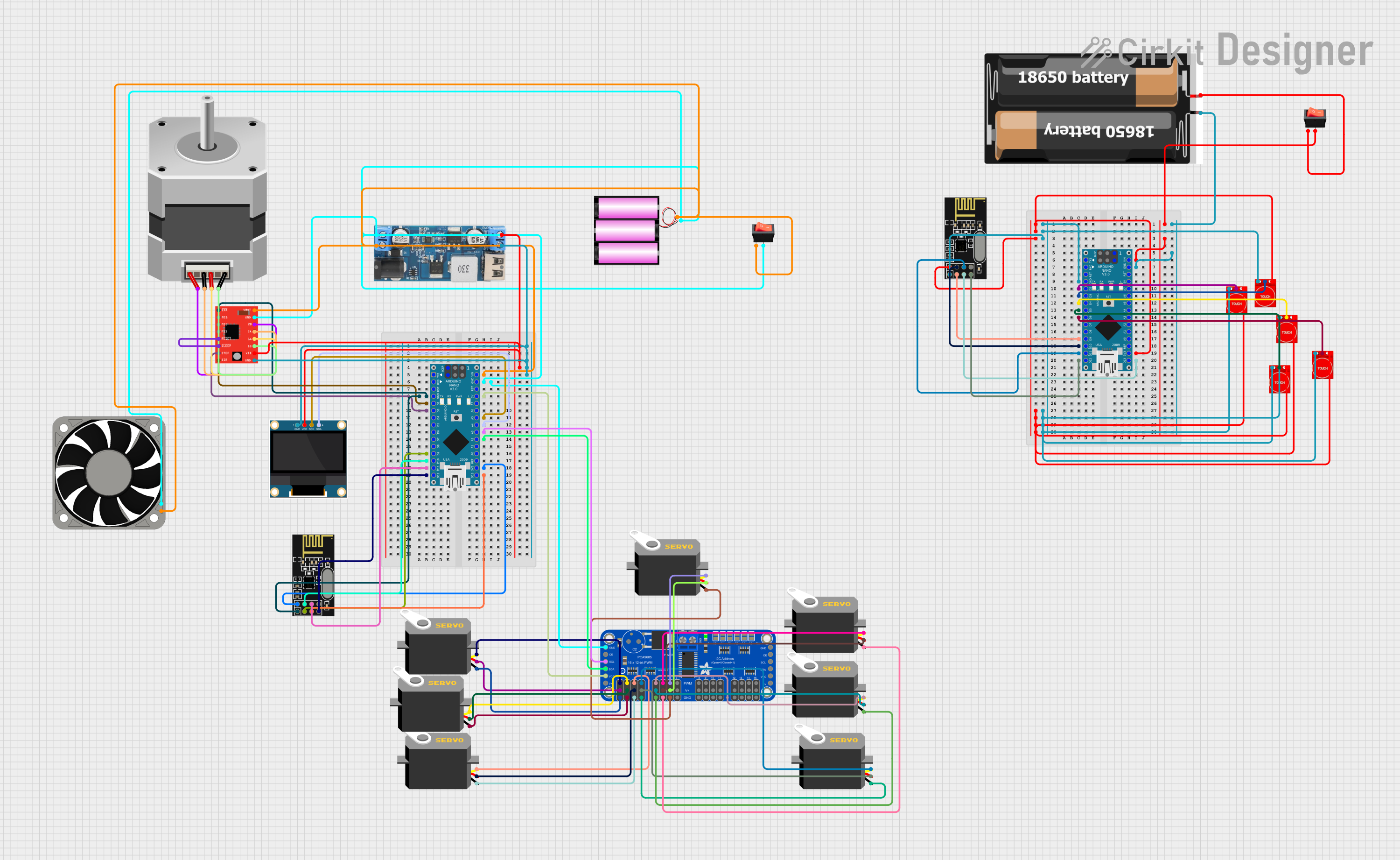 Open Project in Cirkit Designer
Explore Projects Built with 12V PWM 80x80mm Fan
Open Project in Cirkit DesignerOpen Project in Cirkit DesignerOpen Project in Cirkit DesignerOpen Project in Cirkit DesignerCommon Applications
- Cooling for computer cases, CPUs, and GPUs
- Ventilation in power supplies and small enclosures
- Temperature management in embedded systems
- General-purpose cooling for electronic devices
Technical Specifications
Below are the key technical details of the 12V PWM 80x80mm fan:
| Parameter | Specification |
|---|---|
| Operating Voltage | 12V DC |
| Current Consumption | 0.15A (typical) |
| Power Consumption | 1.8W |
| Fan Dimensions | 80mm x 80mm x 25mm |
| Speed Range | 800 - 3000 RPM (PWM controlled) |
| Airflow | Up to 40 CFM |
| Noise Level | 18 - 30 dBA (depending on speed) |
| Connector Type | 4-pin PWM |
| Bearing Type | Sleeve or ball bearing (varies) |
| Operating Temperature | -10°C to 70°C |
| Lifespan | 30,000 - 50,000 hours |
Pin Configuration
The fan's 4-pin connector is configured as follows:
| Pin Number | Wire Color | Function | Description |
|---|---|---|---|
| 1 | Black | Ground (GND) | Connect to the ground of the power supply |
| 2 | Yellow | Power (12V) | Connect to a 12V DC power source |
| 3 | Green | Tachometer (TACH) | Outputs a signal for RPM monitoring |
| 4 | Blue | PWM Control | Accepts a PWM signal for speed control |
Usage Instructions
How to Use the Fan in a Circuit
- Power Connection: Connect the black wire to the ground (GND) and the yellow wire to a 12V DC power source.
- PWM Control: Use the blue wire to provide a PWM signal (typically 25kHz) to control the fan speed. A duty cycle of 0% stops the fan, while 100% runs it at full speed.
- Tachometer Monitoring: The green wire outputs a tachometer signal, which can be used to monitor the fan's RPM. This signal is typically a square wave with two pulses per revolution.
Important Considerations
- Ensure the power supply provides a stable 12V DC output to avoid damaging the fan.
- Use a PWM signal with a frequency of 25kHz for optimal performance.
- Avoid blocking the fan's airflow to maintain cooling efficiency.
- If using the fan with a microcontroller (e.g., Arduino), ensure the PWM pin can output a 25kHz signal.
Example: Using the Fan with an Arduino UNO
Below is an example of how to control the fan speed using an Arduino UNO:
// Example code to control a 12V PWM fan with Arduino UNO
// Ensure the PWM pin supports high-frequency output (e.g., pin 9 or 10)

// Define the PWM pin connected to the fan's blue wire
const int pwmPin = 9;

void setup() {
  // Set the PWM pin as an output
  pinMode(pwmPin, OUTPUT);
}

void loop() {
  // Set fan speed to 50% (duty cycle = 128 out of 255)
  analogWrite(pwmPin, 128);
  delay(5000); // Run at 50% speed for 5 seconds

  // Set fan speed to 100% (duty cycle = 255 out of 255)
  analogWrite(pwmPin, 255);
  delay(5000); // Run at full speed for 5 seconds

  // Set fan speed to 0% (duty cycle = 0 out of 255)
  analogWrite(pwmPin, 0);
  delay(5000); // Stop the fan for 5 seconds
}
Note: The Arduino UNO's default PWM frequency on most pins is ~490Hz, which is too low for this fan. To achieve the required 25kHz frequency, you may need to modify the timer settings. Refer to the Arduino documentation for advanced PWM configuration.
Troubleshooting and FAQs
Common Issues and Solutions
Fan Does Not Spin
- Cause: No power or incorrect wiring.
- Solution: Verify that the black wire is connected to GND and the yellow wire to a 12V DC power source.
Fan Spins at Full Speed Constantly
- Cause: PWM signal not provided or incorrect frequency.
- Solution: Ensure the blue wire is connected to a PWM-capable pin and the signal frequency is 25kHz.
Tachometer Signal Not Detected
- Cause: Incorrect connection or incompatible monitoring circuit.
- Solution: Verify the green wire connection and ensure the monitoring device can read the tachometer signal.
Excessive Noise
- Cause: Fan running at high speed or obstructed airflow.
- Solution: Reduce the PWM duty cycle to lower the speed or clear any obstructions.
FAQs
Q: Can I use this fan with a 5V power supply?
A: No, the fan is designed for 12V operation. Using a lower voltage may prevent it from starting or reduce its performance.
Q: What happens if I don't connect the PWM wire?
A: The fan will run at full speed by default if the PWM wire is left unconnected.
Q: Can I control multiple fans with one PWM signal?
A: Yes, you can control multiple fans with the same PWM signal, but ensure the power supply can handle the combined current draw.
Q: How do I clean the fan?
A: Use compressed air to remove dust and debris. Avoid disassembling the fan, as this may void the warranty.