How to Use OV7670: Examples, Pinouts, and Specs
Introduction
The OV7670 is a low-cost CMOS image sensor capable of capturing video and still images. It features a VGA resolution of 640x480 pixels and supports multiple output formats, including RGB, YUV, and JPEG. This compact and versatile module is widely used in embedded systems, robotics, surveillance, and mobile devices due to its affordability and ease of integration.
Common applications of the OV7670 include:
- Object detection and tracking in robotics
- Video streaming and recording in surveillance systems
- Image capture for machine vision and AI projects
- Educational projects involving image processing and computer vision
Explore Projects Built with OV7670
Explore Projects Built with OV7670
Technical Specifications
The OV7670 image sensor is designed for low-power, high-performance applications. Below are its key technical details:
Key Specifications
| Parameter | Value |
|---|---|
| Resolution | VGA (640x480 pixels) |
| Pixel Size | 3.6 µm x 3.6 µm |
| Output Formats | RGB565, YUV422, JPEG |
| Operating Voltage | 2.5V (analog), 1.8V (core) |
| I/O Voltage | 3.3V |
| Frame Rate | Up to 30 fps |
| Lens Size | 1/6 inch |
| Field of View (FOV) | 25° to 60° (depending on lens) |
| Interface | SCCB (similar to I2C) |
| Operating Temperature | -30°C to 70°C |
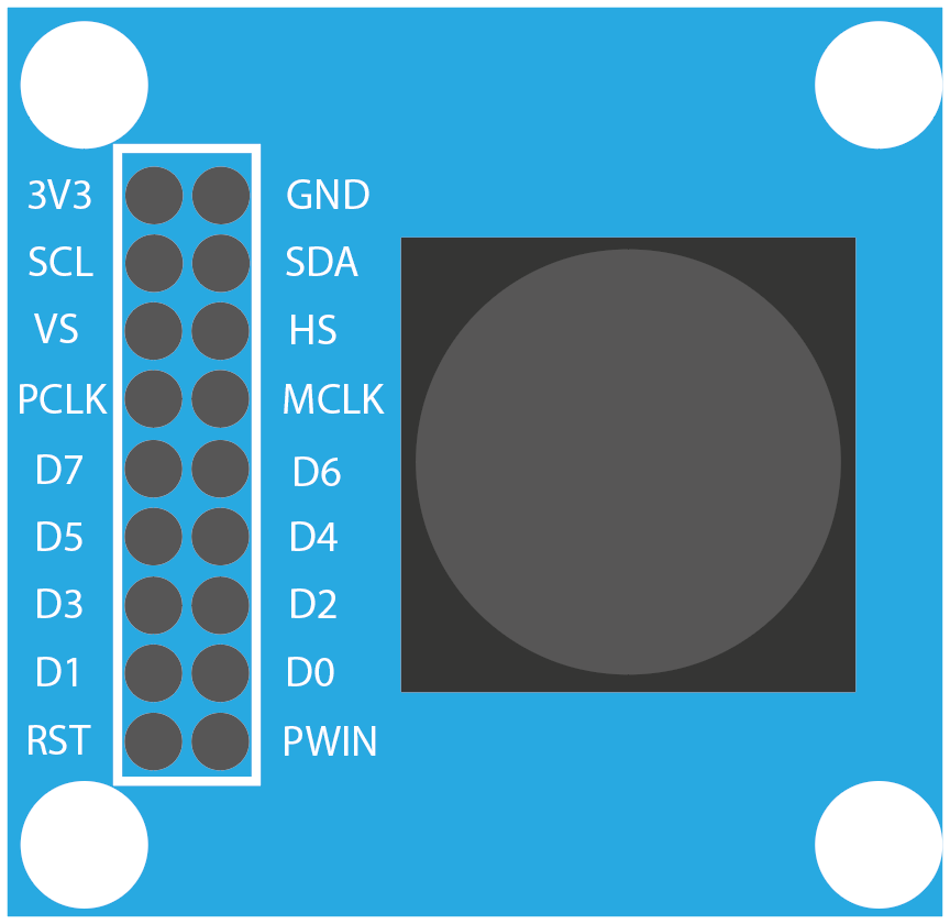
Pin Configuration
The OV7670 module typically comes with a 10-pin interface. Below is the pinout and description:
| Pin Name | Pin Number | Description |
|---|---|---|
| GND | 1 | Ground |
| VCC | 2 | Power supply (3.3V) |
| SCL | 3 | SCCB clock line (similar to I2C SCL) |
| SDA | 4 | SCCB data line (similar to I2C SDA) |
| VSYNC | 5 | Vertical sync signal |
| HREF | 6 | Horizontal reference signal |
| PCLK | 7 | Pixel clock output |
| XCLK | 8 | External clock input (e.g., 24 MHz) |
| D0-D7 | 9-16 | Data output pins (8-bit parallel data) |
| RESET | 17 | Reset signal (active low) |
Usage Instructions
The OV7670 can be integrated into a variety of projects, but it requires careful setup to function correctly. Below are the steps and considerations for using the OV7670 in a circuit:
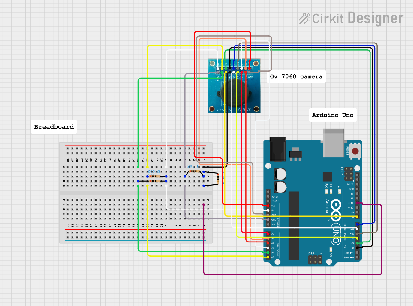
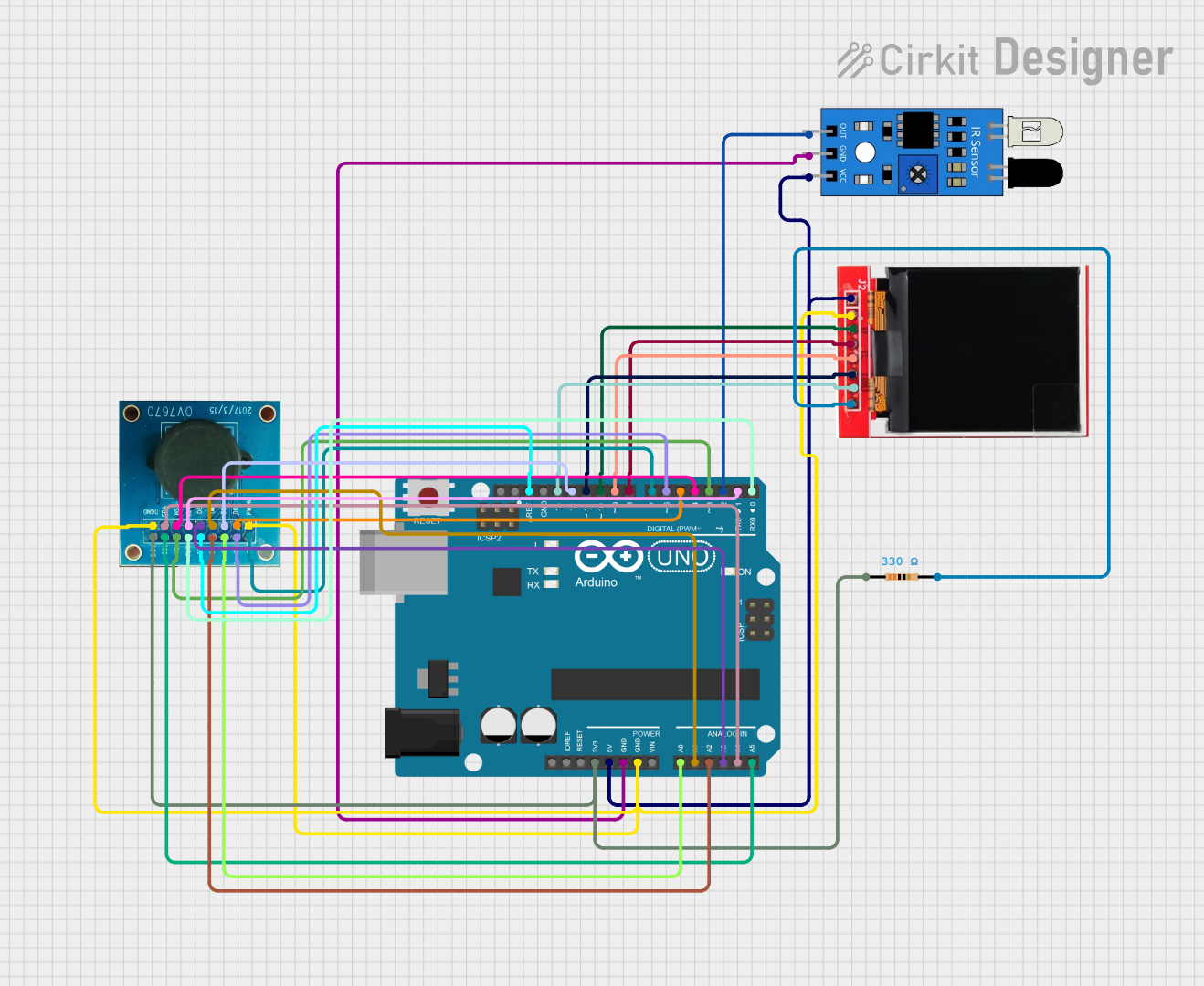
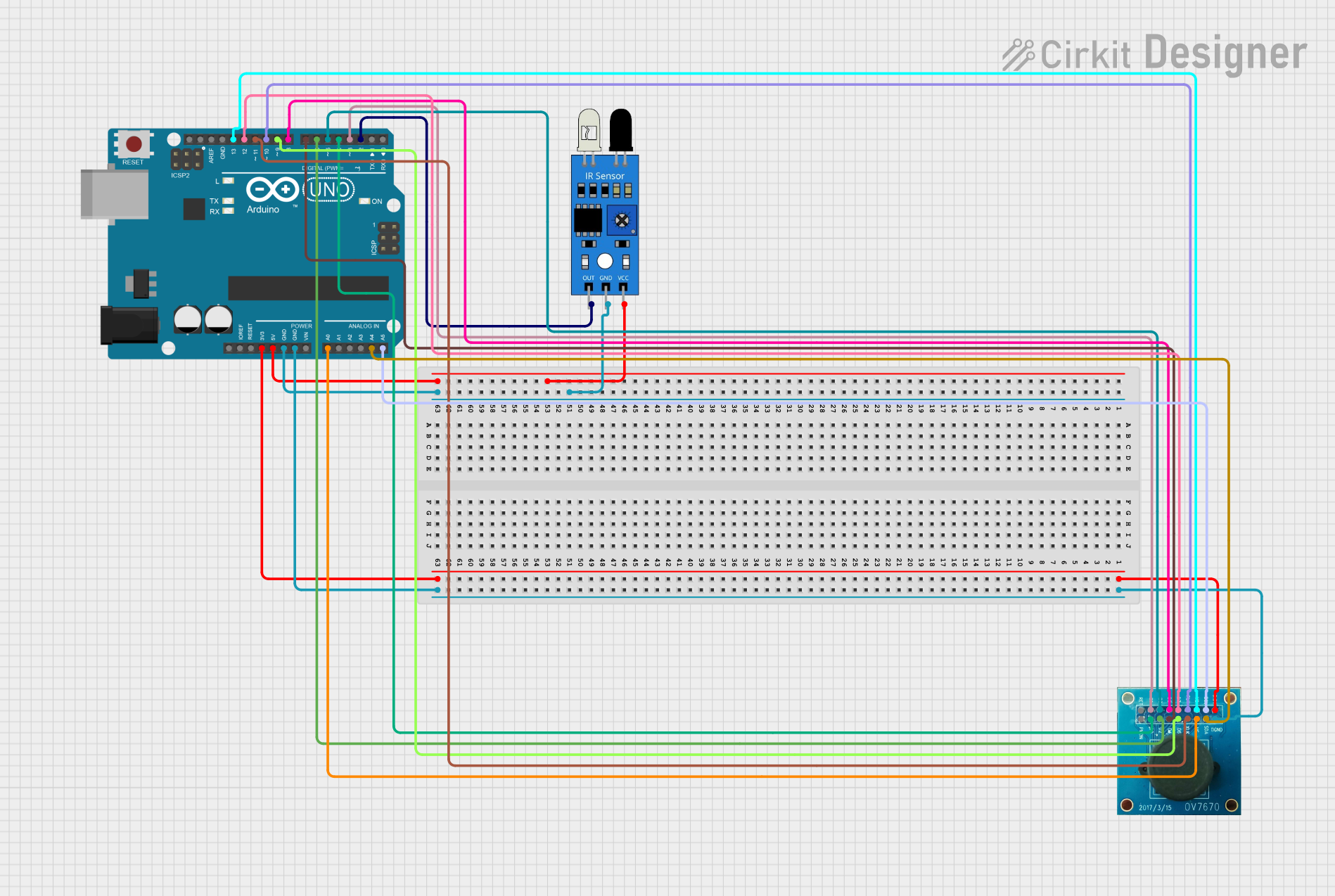
Connecting the OV7670 to an Arduino UNO
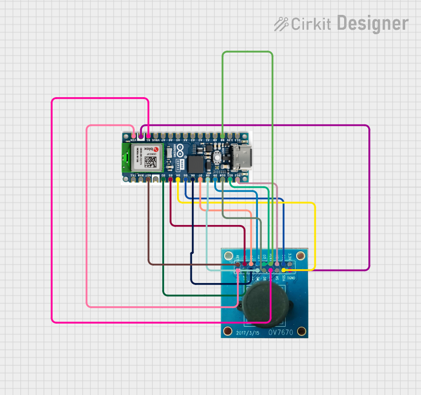
The OV7670 requires an external clock signal (XCLK), which can be generated using a microcontroller like the Arduino UNO. Additionally, the SCCB interface is used to configure the sensor's registers.
Wiring Diagram
| OV7670 Pin | Arduino UNO Pin | Description |
|---|---|---|
| GND | GND | Ground connection |
| VCC | 3.3V | Power supply |
| SCL | A5 | I2C clock line |
| SDA | A4 | I2C data line |
| VSYNC | Digital Pin 2 | Vertical sync signal |
| HREF | Digital Pin 3 | Horizontal reference signal |
| PCLK | Digital Pin 4 | Pixel clock |
| XCLK | Digital Pin 9 | External clock signal |
| D0-D7 | Digital Pins 5-12 | Data output pins (connect as needed) |
| RESET | Digital Pin 13 | Reset signal |
Sample Arduino Code
Below is an example of how to initialize the OV7670 and generate the required XCLK signal using an Arduino UNO:
#include <Wire.h> // Include the Wire library for I2C communication

#define XCLK_PIN 9 // Define the pin for the external clock signal

void setup() {
  pinMode(XCLK_PIN, OUTPUT); // Set XCLK pin as output
  Wire.begin(); // Initialize I2C communication

  // Generate a 24 MHz clock signal on XCLK
  analogWrite(XCLK_PIN, 128); // Use PWM to approximate the clock signal

  // Initialize the OV7670 (configure registers via SCCB/I2C)
  Wire.beginTransmission(0x42 >> 1); // OV7670 I2C address is 0x42
  Wire.write(0x12); // Write to the COM7 register
  Wire.write(0x80); // Reset the sensor
  Wire.endTransmission();

  delay(100); // Wait for the sensor to reset

  // Additional register configurations can be added here
}

void loop() {
  // Main loop for capturing and processing image data
  // This will depend on your specific application
}
Important Considerations
- Clock Signal: The OV7670 requires a stable external clock signal (XCLK). If using an Arduino, PWM can be used to approximate this signal, but a dedicated clock generator is recommended for higher accuracy.
- Voltage Levels: The OV7670 operates at 3.3V. Ensure that all I/O pins are level-shifted if interfacing with a 5V microcontroller.
- Register Configuration: The OV7670 has numerous registers that control its operation. Proper configuration is essential for obtaining the desired output format and resolution.
- Data Handling: The OV7670 outputs image data in an 8-bit parallel format. Ensure your microcontroller or processor can handle this data rate and format.
Troubleshooting and FAQs
Common Issues
No Image Output
- Cause: Incorrect register configuration or wiring.
- Solution: Double-check the SCCB/I2C communication and ensure the sensor is properly initialized.
Distorted or Noisy Image
- Cause: Unstable clock signal or incorrect voltage levels.
- Solution: Use a dedicated clock generator and ensure proper power supply filtering.
Arduino Freezes During Initialization
- Cause: SCCB communication failure.
- Solution: Verify the I2C connections (SCL and SDA) and ensure pull-up resistors are in place.
Image Data Not Captured
- Cause: Incorrect handling of VSYNC, HREF, or PCLK signals.
- Solution: Ensure these signals are correctly connected and processed in your code.
FAQs
Can the OV7670 output JPEG images?
- Yes, the OV7670 supports JPEG output, but additional configuration is required.
What is the maximum frame rate of the OV7670?
- The OV7670 can achieve up to 30 frames per second (fps) at VGA resolution.
Can the OV7670 be used with a Raspberry Pi?
- Yes, the OV7670 can be interfaced with a Raspberry Pi, but additional drivers or libraries may be required for proper operation.
Do I need an external lens for the OV7670?
- The OV7670 typically comes with a built-in lens, but you can replace it with a compatible lens if needed.
By following this documentation, you should be able to successfully integrate the OV7670 into your projects and troubleshoot common issues effectively.