
How to Use BASIC Stamp 2p 40-Pin: Examples, Pinouts, and Specs
 Design with BASIC Stamp 2p 40-Pin in Cirkit Designer
Introduction
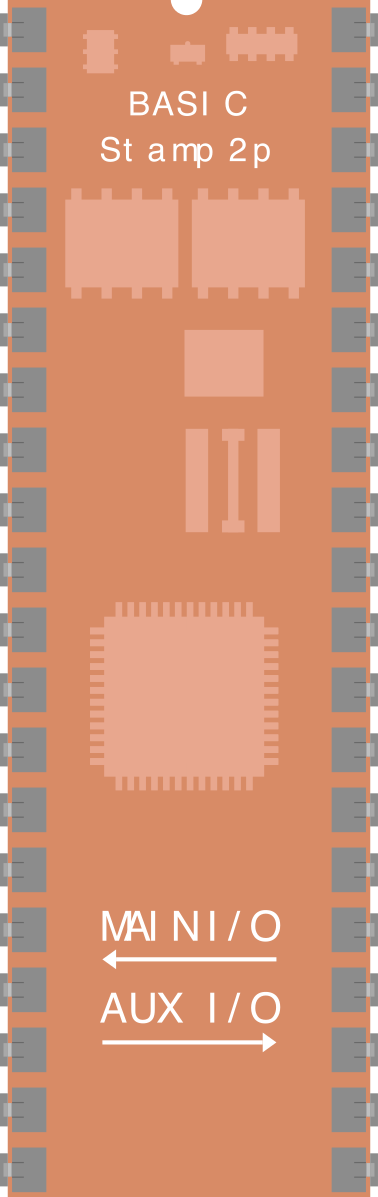
The BASIC Stamp 2p 40-Pin is a microcontroller module housed in a 40-pin DIP (Dual Inline Package) form factor. It is designed for ease of use, making it an excellent choice for educational purposes, prototyping, and hobbyist projects. This module is programmed using PBASIC, a simple yet powerful programming language, and is capable of interfacing with a wide range of sensors, actuators, and other electronic components.
Explore Projects Built with BASIC Stamp 2p 40-Pin
 Open Project in Cirkit Designer
 Open Project in Cirkit Designer
 Open Project in Cirkit Designer
 Open Project in Cirkit Designer
Explore Projects Built with BASIC Stamp 2p 40-Pin
Open Project in Cirkit DesignerOpen Project in Cirkit DesignerOpen Project in Cirkit DesignerOpen Project in Cirkit DesignerCommon Applications and Use Cases
- Robotics and automation projects
- Educational tools for learning microcontroller programming
- Prototyping and proof-of-concept designs
- Home automation systems
- Data acquisition and control systems
Technical Specifications
The BASIC Stamp 2p 40-Pin microcontroller module offers the following key specifications:
| Specification | Details |
|---|---|
| Microcontroller | Parallax SX48AC |
| Operating Voltage | 5V DC |
| Power Supply Range | 5.5V to 15V DC |
| Current Consumption | 3 mA (Run Mode), 50 µA (Sleep Mode) |
| Clock Speed | 20 MHz |
| Program Memory | 2 KB EEPROM (up to 500 PBASIC instructions) |
| RAM | 38 Bytes |
| I/O Pins | 32 (TTL-compatible) |
| Communication Protocols | Serial (TTL-level, 9600 baud default) |
| Dimensions | 2.1" x 0.6" (53.3 mm x 15.2 mm) |
Pin Configuration and Descriptions
The BASIC Stamp 2p 40-Pin module features 40 pins, with the following pin assignments:
| Pin Number | Name | Description |
|---|---|---|
| 1-16 | P0-P15 | General-purpose I/O pins (TTL-compatible) |
| 17-32 | P16-P31 | General-purpose I/O pins (TTL-compatible) |
| 33 | VSS | Ground (0V reference) |
| 34 | VDD | +5V Power Supply |
| 35 | RES | Reset Pin (active low) |
| 36 | VIN | Input Voltage (5.5V to 15V DC) |
| 37 | SOUT | Serial Output (TTL-level) |
| 38 | SIN | Serial Input (TTL-level) |
| 39 | ATN | Attention Pin (used for programming/debugging) |
| 40 | NC | Not Connected |
Usage Instructions
How to Use the BASIC Stamp 2p 40-Pin in a Circuit
- Powering the Module: Connect the VIN pin to a DC power source (5.5V to 15V) and the VSS pin to ground. Alternatively, you can supply regulated 5V directly to the VDD pin.
- Programming: Use the Parallax BASIC Stamp Editor software to write and upload PBASIC code to the module via a serial connection.
- Connecting I/O Devices: Use the P0-P31 pins for interfacing with sensors, LEDs, motors, or other peripherals. Ensure that the connected devices are TTL-compatible or use appropriate level shifters.
- Serial Communication: Use the SIN and SOUT pins for serial communication with other devices or a PC.
Important Considerations and Best Practices
- Power Supply: Ensure the power supply voltage is within the specified range to avoid damaging the module.
- I/O Pin Current: Each I/O pin can source or sink up to 20 mA. Avoid exceeding this limit to prevent damage.
- Pull-Up Resistors: Use pull-up or pull-down resistors as needed for proper operation of input pins.
- Decoupling Capacitors: Place a 0.1 µF capacitor near the VDD and VSS pins to filter noise from the power supply.
Example Code for Interfacing with an LED
The following PBASIC code demonstrates how to blink an LED connected to pin P0:
' BASIC Stamp 2p 40-Pin LED Blink Example
' This code blinks an LED connected to pin P0 with a 1-second interval.

DO
  HIGH 0          ' Set P0 high to turn on the LED
  PAUSE 1000      ' Wait for 1 second
  LOW 0           ' Set P0 low to turn off the LED
  PAUSE 1000      ' Wait for 1 second
LOOP
Example Code for Reading a Push Button
The following PBASIC code reads the state of a push button connected to pin P1 and lights an LED on pin P0 when the button is pressed:
' BASIC Stamp 2p 40-Pin Push Button Example
' This code lights an LED on P0 when a button on P1 is pressed.

DO
  IF IN1 = 1 THEN  ' Check if the button is pressed (P1 is high)
    HIGH 0         ' Turn on the LED (P0)
  ELSE
    LOW 0          ' Turn off the LED (P0)
  ENDIF
LOOP
Troubleshooting and FAQs
Common Issues and Solutions
Module Not Powering On:
- Ensure the power supply voltage is within the specified range (5.5V to 15V).
- Check all power connections, including VIN, VDD, and VSS.
Unable to Upload Code:
- Verify that the serial connection is properly configured and connected to the SIN and SOUT pins.
- Ensure the ATN pin is correctly connected for programming.
- Check that the correct COM port is selected in the BASIC Stamp Editor.
I/O Pins Not Responding:
- Confirm that the connected devices are TTL-compatible.
- Check for loose or incorrect wiring.
- Ensure the PBASIC code is correctly addressing the desired pins.
Serial Communication Issues:
- Verify the baud rate is set to 9600 (default) or matches the configured rate.
- Use proper level shifters if interfacing with non-TTL devices.
FAQs
Q: Can I use the BASIC Stamp 2p 40-Pin with an Arduino?
A: Yes, you can interface the BASIC Stamp with an Arduino using serial communication. Ensure proper voltage level matching between the two devices.
Q: How do I expand the I/O capabilities of the module?
A: You can use I/O expanders like the MCP23017 or shift registers to increase the number of available I/O pins.
Q: What is the maximum program size I can upload?
A: The module supports up to 2 KB of EEPROM memory, which can store approximately 500 PBASIC instructions.
Q: Can I use this module for battery-powered projects?
A: Yes, the module's low power consumption makes it suitable for battery-powered applications. Use a regulated 5V supply or a battery pack within the specified voltage range.