Cirkit Designer Logo
Cirkit Designer
Your all-in-one circuit design IDE
Home / 
Component Documentation

How to Use ESP32 S3 Pico: Examples, Pinouts, and Specs

Image of ESP32 S3 Pico
Cirkit Designer LogoDesign with ESP32 S3 Pico in Cirkit Designer

Introduction

The ESP32 S3 Pico is a compact microcontroller board developed by Arduino, featuring dual-core processing, integrated Wi-Fi, and Bluetooth capabilities. Designed for IoT applications and embedded systems, this board offers high performance, low power consumption, and a small form factor, making it ideal for a wide range of projects, from smart home devices to wearable technology.

Explore Projects Built with ESP32 S3 Pico

Use Cirkit Designer to design, explore, and prototype these projects online. Some projects support real-time simulation. Click "Open Project" to start designing instantly!
Raspberry Pi Pico and ESP32 Wi-Fi Controlled Sensor Interface
Image of pico_esp32: A project utilizing ESP32 S3 Pico in a practical application
This circuit integrates a Raspberry Pi Pico and an ESP32 Wroom Dev Kit, interconnected through various GPIO pins and resistors, to enable communication and control between the two microcontrollers. The ESP32 is powered by a 3.3V supply and shares ground with the Raspberry Pi Pico, while specific GPIO pins are used for data exchange. The provided code sketches for the Raspberry Pi Pico suggest a framework for further development of the system's functionality.
Cirkit Designer LogoOpen Project in Cirkit Designer
ESP32-S3 Based Automated Watering System with Ultrasonic Sensing and Data Logging
Image of galon otomatis telegram: A project utilizing ESP32 S3 Pico in a practical application
This circuit features an ESP32-S3 microcontroller connected to various peripherals including an HC-SR04 ultrasonic sensor, a water flow sensor, an OLED display, a DS3231 real-time clock (RTC), an SD card module, a water pump, a two-channel relay, and a valve solenoid. The ESP32-S3 manages sensor readings, data logging, and controls the water pump and valve via the relay based on sensor inputs. The circuit is designed for monitoring and controlling water flow, likely in an automated irrigation or fluid management system.
Cirkit Designer LogoOpen Project in Cirkit Designer
ESP32-S3 Based Vibration Detection System with TFT Display and Power Backup
Image of IOT Thesis: A project utilizing ESP32 S3 Pico in a practical application
This circuit features an ESP32-S3 microcontroller connected to various peripherals including an ADXL355 accelerometer, an SW-420 vibration sensor, a buzzer module, and an ILI9341 TFT display. The ESP32-S3 manages sensor inputs and provides output to the display and buzzer. Power management is handled by a 12V to 5V step-down converter, and a UPS ensures uninterrupted power supply, with a rocker switch to control the power flow.
Cirkit Designer LogoOpen Project in Cirkit Designer
ESP32-S3 Based Environmental Monitoring and Control System with Data Logging
Image of ESP32: A project utilizing ESP32 S3 Pico in a practical application
This circuit features an ESP32-S3 microcontroller interfaced with various sensors and modules, including a DHT22 temperature and humidity sensor, an HC-SR04 ultrasonic sensor, an SGP41 VOC and NOx sensor, and an Adafruit INA260 current and power sensor. The ESP32-S3 also controls a DC motor via a relay and communicates with an SD card and an OLED display. An Arduino UNO is used to read inputs from a rotary encoder, and a step-down buck converter is used to regulate voltage from a 12V battery to power the components.
Cirkit Designer LogoOpen Project in Cirkit Designer

Explore Projects Built with ESP32 S3 Pico

Use Cirkit Designer to design, explore, and prototype these projects online. Some projects support real-time simulation. Click "Open Project" to start designing instantly!
Image of pico_esp32: A project utilizing ESP32 S3 Pico in a practical application
Raspberry Pi Pico and ESP32 Wi-Fi Controlled Sensor Interface
This circuit integrates a Raspberry Pi Pico and an ESP32 Wroom Dev Kit, interconnected through various GPIO pins and resistors, to enable communication and control between the two microcontrollers. The ESP32 is powered by a 3.3V supply and shares ground with the Raspberry Pi Pico, while specific GPIO pins are used for data exchange. The provided code sketches for the Raspberry Pi Pico suggest a framework for further development of the system's functionality.
Cirkit Designer LogoOpen Project in Cirkit Designer
Image of galon otomatis telegram: A project utilizing ESP32 S3 Pico in a practical application
ESP32-S3 Based Automated Watering System with Ultrasonic Sensing and Data Logging
This circuit features an ESP32-S3 microcontroller connected to various peripherals including an HC-SR04 ultrasonic sensor, a water flow sensor, an OLED display, a DS3231 real-time clock (RTC), an SD card module, a water pump, a two-channel relay, and a valve solenoid. The ESP32-S3 manages sensor readings, data logging, and controls the water pump and valve via the relay based on sensor inputs. The circuit is designed for monitoring and controlling water flow, likely in an automated irrigation or fluid management system.
Cirkit Designer LogoOpen Project in Cirkit Designer
Image of IOT Thesis: A project utilizing ESP32 S3 Pico in a practical application
ESP32-S3 Based Vibration Detection System with TFT Display and Power Backup
This circuit features an ESP32-S3 microcontroller connected to various peripherals including an ADXL355 accelerometer, an SW-420 vibration sensor, a buzzer module, and an ILI9341 TFT display. The ESP32-S3 manages sensor inputs and provides output to the display and buzzer. Power management is handled by a 12V to 5V step-down converter, and a UPS ensures uninterrupted power supply, with a rocker switch to control the power flow.
Cirkit Designer LogoOpen Project in Cirkit Designer
Image of ESP32: A project utilizing ESP32 S3 Pico in a practical application
ESP32-S3 Based Environmental Monitoring and Control System with Data Logging
This circuit features an ESP32-S3 microcontroller interfaced with various sensors and modules, including a DHT22 temperature and humidity sensor, an HC-SR04 ultrasonic sensor, an SGP41 VOC and NOx sensor, and an Adafruit INA260 current and power sensor. The ESP32-S3 also controls a DC motor via a relay and communicates with an SD card and an OLED display. An Arduino UNO is used to read inputs from a rotary encoder, and a step-down buck converter is used to regulate voltage from a 12V battery to power the components.
Cirkit Designer LogoOpen Project in Cirkit Designer

Common Applications and Use Cases

  • Internet of Things (IoT) devices
  • Smart home automation systems
  • Wearable electronics
  • Wireless sensor networks
  • Robotics and control systems
  • Real-time data monitoring and logging

Technical Specifications

The ESP32 S3 Pico is built to deliver robust performance while maintaining energy efficiency. Below are its key technical specifications:

Specification Details
Microcontroller ESP32-S3 (dual-core Xtensa LX7 processor)
Clock Speed Up to 240 MHz
Flash Memory 8 MB (external)
RAM 512 KB SRAM
Wireless Connectivity Wi-Fi 802.11 b/g/n (2.4 GHz), Bluetooth 5.0 LE
GPIO Pins 27 (multipurpose, including ADC, DAC, I2C, SPI, UART, PWM)
Operating Voltage 3.3V
Input Voltage Range 5V (via USB-C)
Power Consumption Ultra-low power modes available
USB Interface USB-C (supports programming and power supply)
Dimensions 21 mm x 51 mm

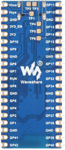
Pin Configuration and Descriptions

The ESP32 S3 Pico features a versatile pinout, allowing for multiple configurations. Below is the pin configuration:

Pin Name Function
1 GND Ground
2 3V3 3.3V power output
3 EN Enable pin (active high, resets the board when pulled low)
4 GPIO0 General-purpose I/O, boot mode selection
5 GPIO1 General-purpose I/O, UART TX
6 GPIO2 General-purpose I/O, UART RX
7 GPIO3 General-purpose I/O, ADC, PWM
8 GPIO4 General-purpose I/O, ADC, PWM
9 GPIO5 General-purpose I/O, SPI MOSI
10 GPIO6 General-purpose I/O, SPI MISO
... ... ... (Refer to the official datasheet for the full pinout)

Usage Instructions

The ESP32 S3 Pico is easy to integrate into your projects. Below are the steps to get started and important considerations:

How to Use the ESP32 S3 Pico in a Circuit

  1. Powering the Board:

    • Connect the board to your computer or power source using a USB-C cable.
    • Ensure the input voltage does not exceed 5V to avoid damage.
  2. Programming the Board:

    • Install the Arduino IDE and add the ESP32 board package via the Board Manager.
    • Select "ESP32 S3 Pico" as the target board in the Tools menu.
    • Write your code and upload it to the board using the USB-C connection.
  3. Connecting Peripherals:

    • Use the GPIO pins to connect sensors, actuators, or other peripherals.
    • Ensure proper voltage levels (3.3V logic) when interfacing with external components.

Important Considerations and Best Practices

  • Power Supply: Always use a stable power source to avoid unexpected resets or malfunctions.
  • Pin Voltage Levels: The GPIO pins operate at 3.3V logic. Avoid applying 5V directly to the pins.
  • Wi-Fi and Bluetooth: Ensure proper antenna placement for optimal wireless performance.
  • Heat Management: While the ESP32 S3 Pico is efficient, prolonged high-performance tasks may generate heat. Consider ventilation if necessary.

Example Code for Arduino UNO Integration

Below is an example of how to use the ESP32 S3 Pico to read data from a DHT11 temperature and humidity sensor and send it to a serial monitor:

#include <DHT.h>

// Define the DHT sensor type and pin
#define DHTPIN 4       // GPIO4 is connected to the DHT11 data pin
#define DHTTYPE DHT11  // DHT11 sensor type

DHT dht(DHTPIN, DHTTYPE);

void setup() {
  Serial.begin(115200);  // Initialize serial communication at 115200 baud
  dht.begin();           // Initialize the DHT sensor
  Serial.println("DHT11 Sensor Test");
}

void loop() {
  delay(2000);  // Wait 2 seconds between readings

  // Read temperature and humidity values
  float humidity = dht.readHumidity();
  float temperature = dht.readTemperature();

  // Check if the readings are valid
  if (isnan(humidity) || isnan(temperature)) {
    Serial.println("Failed to read from DHT sensor!");
    return;
  }

  // Print the readings to the serial monitor
  Serial.print("Humidity: ");
  Serial.print(humidity);
  Serial.print("%  Temperature: ");
  Serial.print(temperature);
  Serial.println("°C");
}

Troubleshooting and FAQs

Common Issues and Solutions

  1. Board Not Detected by Arduino IDE:

    • Ensure the correct USB driver is installed for the ESP32 S3 Pico.
    • Check that the USB-C cable supports data transfer (not just charging).
    • Verify that the correct board and port are selected in the Arduino IDE.
  2. Wi-Fi Connection Fails:

    • Double-check the SSID and password in your code.
    • Ensure the Wi-Fi network operates on the 2.4 GHz band (not 5 GHz).
    • Place the board closer to the router to improve signal strength.
  3. Program Upload Fails:

    • Press and hold the "BOOT" button on the board while uploading the code.
    • Ensure no other application is using the COM port.
  4. Overheating:

    • Avoid running high-power tasks continuously without breaks.
    • Ensure proper ventilation around the board.

FAQs

Q: Can the ESP32 S3 Pico operate on battery power?
A: Yes, the board can be powered using a 3.7V LiPo battery connected to the appropriate pins, but ensure proper voltage regulation.

Q: Is the ESP32 S3 Pico compatible with Arduino libraries?
A: Yes, most Arduino libraries are compatible with the ESP32 S3 Pico. However, some may require minor modifications.

Q: How do I reset the board?
A: Press the "EN" button on the board to reset it.

Q: Can I use the ESP32 S3 Pico for machine learning applications?
A: Yes, the dual-core processor and ample memory make it suitable for lightweight machine learning tasks.

This concludes the documentation for the ESP32 S3 Pico. For further details, refer to the official Arduino documentation or datasheet.