
How to Use SMPS_9V_UP15S09: Examples, Pinouts, and Specs
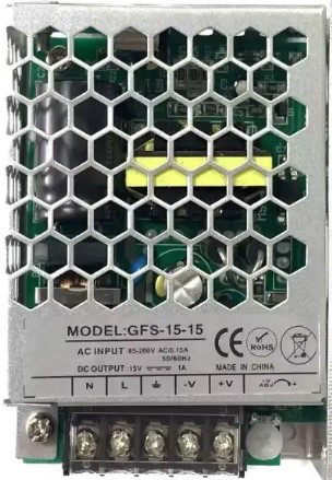
 Design with SMPS_9V_UP15S09 in Cirkit Designer
Introduction
The SMPS_9V_UP15S09, manufactured by GPS, is a switched-mode power supply (SMPS) designed to convert a wide range of input voltages into a stable 9V DC output. This component is highly efficient, compact, and reliable, making it ideal for powering low-power electronic devices, microcontrollers, and other circuits requiring a regulated 9V supply. Its robust design ensures minimal heat generation and high energy efficiency, even under varying load conditions.
Explore Projects Built with SMPS_9V_UP15S09
 Open Project in Cirkit Designer
 Open Project in Cirkit Designer
 Open Project in Cirkit Designer
 Open Project in Cirkit Designer
Explore Projects Built with SMPS_9V_UP15S09
Open Project in Cirkit DesignerOpen Project in Cirkit DesignerOpen Project in Cirkit DesignerOpen Project in Cirkit DesignerCommon Applications and Use Cases
- Powering microcontroller boards (e.g., Arduino, Raspberry Pi with 9V input)
- Battery-powered devices requiring efficient voltage regulation
- Portable electronics and embedded systems
- Industrial control systems
- Replacement for linear voltage regulators to improve efficiency
Technical Specifications
The following table outlines the key technical details of the SMPS_9V_UP15S09:
| Parameter | Value |
|---|---|
| Input Voltage Range | 85V AC to 265V AC (universal input) |
| Output Voltage | 9V DC |
| Output Current | Up to 1.5A |
| Output Power | 13.5W |
| Efficiency | ≥ 85% |
| Ripple and Noise | ≤ 50mV |
| Operating Temperature | -25°C to +70°C |
| Storage Temperature | -40°C to +85°C |
| Dimensions | 50mm x 25mm x 20mm |
| Weight | 30g |
| Protection Features | Overload, Overvoltage, Short Circuit |
Pin Configuration and Descriptions
The SMPS_9V_UP15S09 has four primary pins for input and output connections. The table below describes each pin:
| Pin Name | Description |
|---|---|
| AC_IN1 | AC input terminal 1 (Live or Neutral) |
| AC_IN2 | AC input terminal 2 (Live or Neutral) |
| DC_OUT+ | Positive 9V DC output |
| DC_OUT- | Negative (Ground) 9V DC output |
Usage Instructions
How to Use the SMPS_9V_UP15S09 in a Circuit
- Input Connection: Connect the AC_IN1 and AC_IN2 pins to the AC mains supply (85V to 265V AC). Ensure proper insulation and safety precautions when handling high-voltage AC connections.
- Output Connection: Connect the DC_OUT+ and DC_OUT- pins to the load or circuit requiring a 9V DC supply. Verify the polarity to avoid damage to the connected device.
- Mounting: Secure the SMPS module in a well-ventilated area to prevent overheating. Avoid placing it near heat-sensitive components.
- Testing: Before connecting the load, measure the output voltage using a multimeter to ensure it is stable at 9V DC.
Important Considerations and Best Practices
- Safety First: Always disconnect the power supply before making any connections or modifications.
- Load Requirements: Ensure the connected load does not exceed the maximum output current of 1.5A.
- Heat Dissipation: Although the SMPS is efficient, it may generate some heat under heavy loads. Use proper ventilation or a heatsink if necessary.
- Noise Filtering: If the connected circuit is sensitive to noise, consider adding a capacitor (e.g., 100µF electrolytic) across the output terminals to further reduce ripple and noise.
- Arduino Compatibility: The SMPS_9V_UP15S09 can be used to power an Arduino UNO or similar boards via the VIN pin, which accepts 7-12V DC.
Example: Powering an Arduino UNO
Below is an example of how to connect the SMPS_9V_UP15S09 to an Arduino UNO:
- Connect the DC_OUT+ pin of the SMPS to the VIN pin of the Arduino UNO.
- Connect the DC_OUT- pin of the SMPS to the GND pin of the Arduino UNO.
- Ensure the input AC voltage is within the specified range.
// Example Arduino code to blink an LED when powered by SMPS_9V_UP15S09
// Connect an LED to pin 13 with a 220-ohm resistor

void setup() {
  pinMode(13, OUTPUT); // Set pin 13 as an output
}

void loop() {
  digitalWrite(13, HIGH); // Turn the LED on
  delay(1000);            // Wait for 1 second
  digitalWrite(13, LOW);  // Turn the LED off
  delay(1000);            // Wait for 1 second
}
Troubleshooting and FAQs
Common Issues and Solutions
| Issue | Possible Cause | Solution |
|---|---|---|
| No output voltage | Incorrect input connection | Verify AC_IN1 and AC_IN2 connections. |
| Output voltage is unstable or noisy | Load exceeds maximum current rating | Reduce the load to within 1.5A limit. |
| Excessive heat generation | Poor ventilation or high ambient temperature | Improve ventilation or reduce load. |
| Device not powering on | Faulty connections or damaged component | Check all connections and replace if needed. |
FAQs
Can I use this SMPS to power a 12V device?
- No, the SMPS_9V_UP15S09 provides a fixed 9V output. Using it for a 12V device may result in insufficient power or malfunction.
Is the SMPS_9V_UP15S09 safe for outdoor use?
- The module is not weatherproof. Use it indoors or in a sealed, weatherproof enclosure for outdoor applications.
What happens if the input voltage exceeds 265V AC?
- The SMPS is designed to handle up to 265V AC. Exceeding this limit may damage the module or trigger its protection features.
Can I use this SMPS with a battery as input?
- No, this SMPS is designed for AC input only. For battery-powered applications, consider a DC-DC converter instead.
By following this documentation, users can safely and effectively integrate the SMPS_9V_UP15S09 into their projects.